Nissan Rogue Service Manual: Key interlock cable
Exploded View
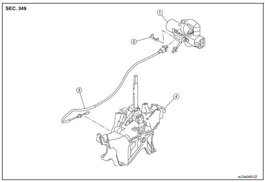
- Key cylinder
- Clip
- Key interlock cable
- Shift selector assembly
Removal and Installation
REMOVAL
CAUTION: Always apply the parking brake before performing removal and installation.
- Move shift selector to the “N” position.
- Remove the shift selector knob.
- Move shift selector to the “P” position.
- Remove the center console assembly. Refer to IP-18, "Removal and Installation".
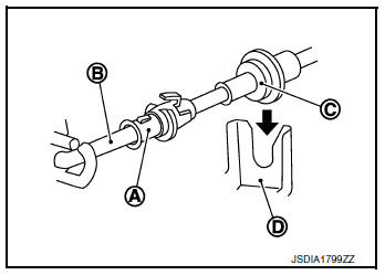
- Press the pawls (B) of the key interlock cable slider (A) while sliding it in the direction of the casing cap (C), and separate the adjusting holder (D) and slider.
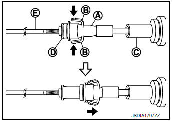
(E) :Key interlock rod
- Remove the key interlock cable from the shift selector.
- Remove the steering column covers. Refer to IP-17, "Removal and Installation".
- Remove instrument lower panel LH. Refer to IP-22, "Removal and Installation".
- Lift clip (A) in the direction of the arrow (
 C) and remove in the
direction of the arrow (
C) and remove in the
direction of the arrow (  D).
D).
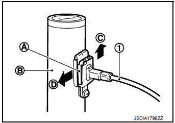
(1) :Key interlock cable
(B) :Key cylinder
- Disconnect the key interlock cable from the key cylinder.
- Disengage the clip and disconnect the key interlock cable from the vehicle.
INSTALLATION
Installation is in the reverse order of removal.
- While pressing the detent rod (B) down ( ), slide the key interlock cable slider (A) toward the key interlock rod (D) side, and install the adjusting holder (C) and key interlock rod.
CAUTION:
- Do not squeeze the pawls on the key interlock cable slider when holding the slider.
- Do not apply force in a perpendicular direction to the key interlock rod when sliding the slider.
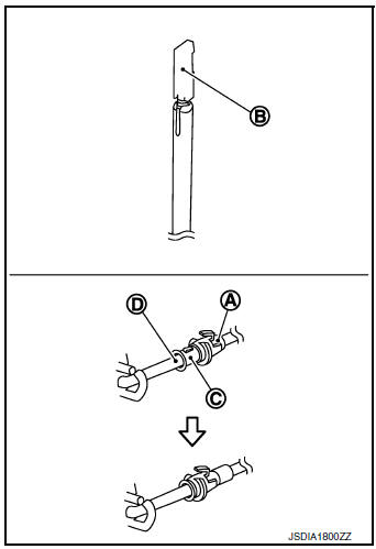
- Install the adjusting holder (A) onto the key interlock rod (B), then install the casing cap (C) onto the shift selector cable bracket (D).
CAUTION:
- When installing the key interlock cable, do not bend or twist the cable forcefully.
- After connecting the key interlock cable to the shift selector cable bracket, be sure to check that the casing cap is completely fastened to the cable bracket. If the casing cap is easily displaced, replace the key interlock cable.
Inspection
INSPECTION AFTER INSTALLATION
- Check the CVT position. If a malfunction is found, adjust the CVT position. Refer to TM-92, "Inspection".
- The key can be removed only when the selector lever is in the “P” position.
- It must not be possible to turn the ignition switch to LOCK when the selector lever is not in the “P” position
 Control cable
Exploded View
Shift selector
Control cable
Retainer grommet
Lock plate
Bracket
Manual lever
Transaxle assembly
Front
Removal and Installation
CAUTION:
Always apply ...
 TCM
TCM
Exploded View
Bracket
Bracket
TCM
: Vehicle front
: N·m (kg-m, in-lb)
Removal and Installation
CAUTION:
Do not impact the TCM when removing or installing TCM.
Wh ...
Other materials:
Precaution
Precaution for Supplemental Restraint System (SRS) "AIR BAG" and "SEAT
BELT
PRE-TENSIONER"
with a front seat belt, helps to reduce the risk or severity of injury to the
driver and front passenger for certain
types of collision. Information necessary to service the system s ...
How to read the displayed lines
Guiding lines which indicate the vehicle width
and distances to objects with reference to the
vehicle body line A are displayed on the monitor.
Distance guide lines:
Indicate distances from the vehicle body.
Red line 1 : approx. 0.5 m (1.5 ft)
Yellow line 2 : approx. 1 m (3 ...
Preparation
Special Service Tool
The actual shape of the tools may differ from those illustrated here.
Tool number
(TechMate No.)
Tool name
Description
—
(J-46534)
Trim Tool Set
Removing trim components
Commercial Service Too
(TechMate No.)
...
