Nissan Rogue Service Manual: Inside mirror
Exploded View
MANUAL ANTI-DAZZLING
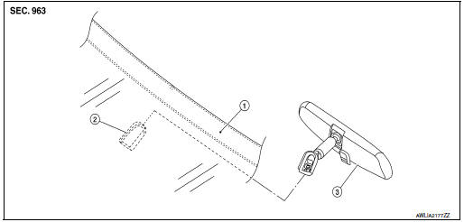
- Windshield glass
- Mirror base
- Inside mirror
AUTO ANTI-DAZZLING
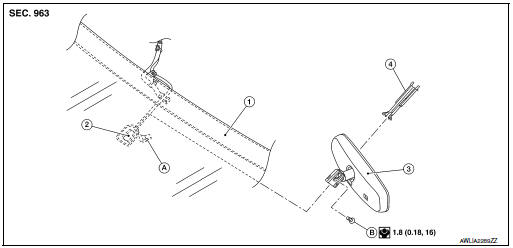
- Windshield glass
- Mirror base
- Inside mirror
- Inside mirror finisher
- Harness connector
- Bolt
Removal and Installation
MANUAL ANTI-DAZZLING
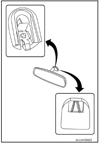
Removal
- Hold inside mirror at the base and push upward, while using a suitable tool to release the pawl and remove.
CAUTION: Use care when removing inside mirror to avoid damage to mirror, mirror base or windshield glass.
Installation
Installation is in the reverse order of removal.
CAUTION: Apply Genuine Mirror Adhesive or equivalent to bonding surface of mirror base if loose or removed.
Refer to GI-22, "Recommended Chemical Products and Sealants".
AUTO ANTI-DAZZLING
Removal
- Remove inside mirror finisher.
- Disconnect the harness connector from the inside mirror.
- Loosen bolt and slide inside mirror upward to remove.
Installation
Installation is in the reverse order of removal.
- Calibrate compass (if equipped).
CAUTION: Apply Genuine Mirror Adhesive or equivalent to bonding surface of mirror base if loose or removed.
Refer to GI-22, "Recommended Chemical Products and Sealants".
NOTE: Calibrate the compass by driving the vehicle in a complete circle three times.

 Door mirror
Exploded View
Door mirror
Door mirror corner finisher
Door mirror rear finisher
Side turn signal lamp
Side camera (if equipped)
Door mirror glass
Pawl
Removal an ...
Other materials:
Starting the engine (models without NISSAN
Intelligent Key® system)
Apply the parking brake.
Move the shift lever to P (Park) or N (Neutral).
P (Park) is recommended.
The shift lever cannot be moved out of
P (Park) and into any of the other gear
positions if the ignition key is turned to
the OFF position or if the key is removed
from the ignition ...
Bluetooth® Hands-Free Phone System with Navigation System (if so equipped)
WARNING
Use a phone after stopping your vehicle
in a safe location. If you have to use a
phone while driving, exercise extreme
caution at all times so full attention may
be given to vehicle operation.
If you are unable to devote full attention
to vehicl ...
Wiring diagram
MOONROOF SYSTEM
Wiring Diagram
...
