Nissan Rogue Owners Manual: Hill Descent Control System (if so equipped)
Hill Descent Control System
WARNING
|
The hill descent control system can only be activated when the AWD LOCK switch is engaged.
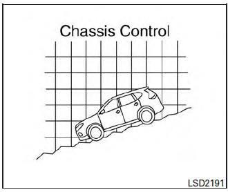
The hill descent control system helps maintain vehicle speed when driving under 15 MPH (25 km/h) on steeper downhill grades. Hill descent control is useful when engine braking alone cannot control vehicle speed. Hill descent control applies the vehicle brakes to control vehicle speed allowing the driver to concentrate on steering while reducing the burden of brake and accelerator operation.
If the hill descent control light is blinking, the hill descent control is engaged; however, the hill descent control will not control the vehicle speed.
- When additional braking is required on steep downhill roads, activate the hill descent control system by pushing the switch ON. For additional information, refer to “Hill descent control switch” in the “Instruments and controls” section of this manual.
- Once the system is activated, the indicator
light will remain on in the instrument panel.
For additional information, refer to “Hill descent control system on indicator light” in the “Instruments and controls” section of this manual.
If the accelerator or brake pedal is depressed while the hill descent control system is on, the system will stop operating temporarily. As soon as the accelerator or brake pedal is released, the hill descent control system begins to function again if the hill descent control operating conditions are fulfilled.
For the best results, when descending steep downhill grades, the hill descent control switch should be ON and the shift lever in L (Low gear) for engine braking.
 Active ride control
This system senses upper body motion (based
on wheel speed information) and controls engine
torque and four wheel brake pressure. This will
enhance ride comfort in effort to restrain uncomfortable
...
 Hill start assist system
Hill start assist system
WARNING
Never rely solely on the hill start assist
system to prevent the vehicle from moving
backward on a hill. Always drive
carefully and a ...
Other materials:
DTC/circuit diagnosis
POWER SUPPLY AND GROUND CIRCUIT
BCM (BODY CONTROL SYSTEM) (WITH INTELLIGENT KEY SYSTEM)
BCM (BODY CONTROL SYSTEM) (WITH INTELLIGENT KEY SYSTEM) : Diagnosis
Procedure
Regarding Wiring Diagram information, refer to BCS-50, "Wiring Diagram".
1. CHECK FUSE
Check that the following fuse i ...
U1000 CAN COMM circuit
Description
CAN (Controller Area Network) is a serial communication system for real time
application. It is an on-vehicle
multiplex communication system with high data communication speed and excellent
error detection ability.
Many electronic control units are equipped into vehicles, and ea ...
U1010 control unit (CAN)
DTC Logic
DTC DETECTION LOGIC
DTC
Display Item
Malfunction Detected Condition
Possible cause
U1010
CONTROL UNIT (CAN)
BCM detected internal CAN communication circuit malfunction.
BCM
Diagnosis Procedure
1.REPLACE BCM
When DTC “U1010” is detected, repla ...
