Nissan Rogue Service Manual: Front wiper arm
Exploded View
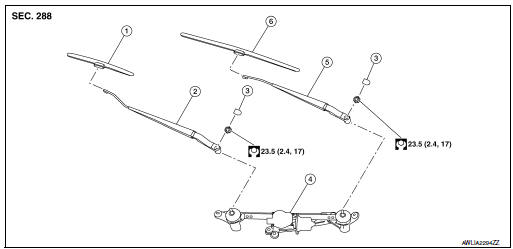
- Front wiper blade (RH)
- Front wiper arm (RH)
- Front wiper arm cover
- Front wiper drive assembly
- Front wiper arm (LH)
- Front wiper blade (LH)
Removal and Installation
REMOVAL
- Move front wiper into the service position by turning the ignition switch ON, then quickly push the wiper washer switch to the mist position two times within 0.5 seconds.
- Turn the ignition switch OFF.
- Remove front wiper arm covers.
- Remove nuts and remove front wiper arms.
INSTALLATION
- Clean wiper arm mount as shown in the figure to prevent nuts from being loosened.

- Move front wiper into the service position by turning the ignition switch ON, then quickly push the wiper washer switch to the mist position two times within 0.5 seconds.
- Turn the ignition switch OFF.
- Adjust front wiper blade position. Refer to WW-64, "Adjustment".
- Install front wiper arm by tightening the nuts.
- Install front wiper arm covers.
- Check that the front wiper blades stop at the specified position.
Adjustment
- Wiper blade (RH)
- Front fender (RH)
- Windshield glass
- Cowl top cover
- Wiper blade (LH)
- 34.9 ± 7.5 mm (1.4 ± 0.3 in)
- 38.2 ± 7.5 mm (1.5 ± 0.3 in)
 Front washer nozzle and tube
Exploded View
Cowl top cover
Front washer tube
Front washer nozzle (LH)
Front washer nozzle (RH)
Pawl
Clip
Exploded View
Cowl top cover
Front washer tube
...
 Front wiper blade
Exploded View
Wiper blade (RH)
Wiper arm (RH)
Wiper arm cover
Front wiper drive assembly
Wiper arm (LH)
Wiper blade (LH)
Removal and Installation
REMOVAL
Move front ...
Other materials:
Parking brake control
Exploded View
Parking brake rear cable (RH)
Parking brake rear cable (LH)
Parking brake front cable
Parking brake control
Adjusting nut
Parking brake switch
Removal and Installation
REMOVAL
Remove instrument lower panel LH. Refer to IP-22, "Removal and ...
Preparation
Special Service Tool
The actual shape of the tools may differ from those illustrated here.
Tool number
(TechMate No.)
Tool name
Description
—
(J-39570)
Chassis Ear
Locating the noise
—
(J-50397)
NISSAN Squeak and Rattle Kit
...
Removal and installation
NATS ANTENNA AMP.
Removal and Installation
REMOVAL
Remove the steering column covers. Refer to IP-17, "Removal and
Installation".
Disconnect the harness connector from the NATS antenna amp.
Release pawls and remove NATS antenna amp. (1) from the
ignition sw ...
