Nissan Rogue Service Manual: Front washer nozzle and tube
Exploded View
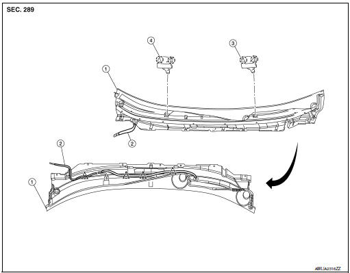
- Cowl top cover
- Front washer tube
- Front washer nozzle (LH)
- Front washer nozzle (RH)
 Pawl
Pawl
 Clip
Clip
Exploded View
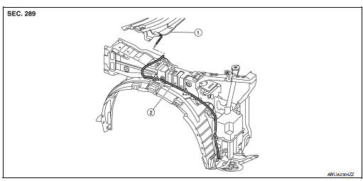
- Cowl top cover
- Front washer tube
Clip
Removal and Installation - Front Washer Nozzle
REMOVAL
- Remove front wiper arms (LH/RH). Refer to WW-63, "Removal and Installation".
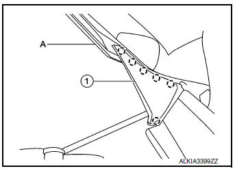
- Release pawls using suitable tool (A) and remove cowl top side
trim cover (1) (LH/RH).: Pawl
- Disconnect front washer tube connector.
- Release pawls and remove front washer nozzle (LH/RH).
INSTALLATION
Installation is in the reverse order of removal.
CAUTION: Adjust the nozzle spray pattern. Refer to WW-61, "Inspection and Adjustment".
Removal and Installation - Front Washer Tube
REMOVAL
- Disconnect front washer tube connector.
- Remove engine side cover. Refer to EXT-28, "FENDER PROTECTOR : Exploded View".
- Remove engine undercover. Refer to EXT-37, "ENGINE UNDER COVER : Removal and Installation".
- Partially remove fender protector. Refer to EXT-28, "FENDER PROTECTOR : Exploded View".
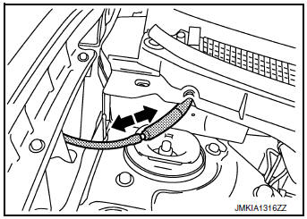
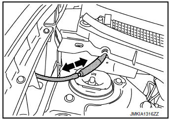
- Unclip front washer hose and remove.
INSTALLATION
Installation is in the reverse order of removal.
Inspection and Adjustment
WASHER TUBE INSPECTION
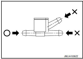
Check that air can pass through the check valve splitter by blowing into the check valve splitter and that air cannot flow in the opposite direction.
O: Air can flow
X: Air cannot flow
ADJUSTMENT
If operating properly, spray positions should match the positions shown. If spray positions do not match, confirm the rear washer nozzle is properly seated and working properly. If the spray positions still do not match as shown, then replace the front washer nozzle. Refer to WW-60, "Removal and Installation - Front Washer Nozzle"
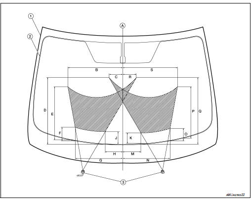
- Windshield glass
- Black printed area line
- Front washer nozzle (LH/RH)
- Center line
- 409 mm (16.10 in)
- 103 mm (4.06 in)
- 497 mm (19.57 in)
- 398 mm (15.67 in)
- 100 mm (3.94 in)
- 356 mm (14.02 in)
- 127 mm (5.00 in)
- 93 mm (3.66 in)
- 80 mm (3.15 in)
- 133 mm (5.24 in)
- 354 mm (13.94 in)
- 90 mm (3.54 in)
- 380 mm (14.96 in)
- 496 mm (19.53 in)
- 103 mm (4.06 in)
- 409 mm (16.10 in)
 Washer fluid level switch
Removal and Installation
The washer fluid level switch is serviced as a part of the washer tank. Refer
to WW-56, "Removal and Installation". ...
 Front wiper arm
Exploded View
Front wiper blade (RH)
Front wiper arm (RH)
Front wiper arm cover
Front wiper drive assembly
Front wiper arm (LH)
Front wiper blade (LH)
Removal ...
Other materials:
Precaution
Precaution for Supplemental Restraint System (SRS) "AIR BAG" and "SEAT
BELT
PRE-TENSIONER"
The Supplemental Restraint System such as “AIR BAG” and “SEAT BELT PRE-TENSIONER”,
used along
with a front seat belt, helps to reduce the risk or severity of injury to the
...
P052A, P052B intake valve timing control
DTC Description
DTC DETECTION LOGIC
DTC No.
CONSULT screen terms
(Trouble diagnosis content)
DTC detecting condition
P052A
CAMSHAFT POSITION TIMING B1
(Cold start “A” camshaft position timing
over-advanced bank 1)
There is a gap between angle of target and ...
Precautions on child restraints
WARNING
Failure to follow the warnings and instructions
for proper use and installation
of child restraints could result in
serious injury or death of a child or
other passengers in a sudden stop or
collision:
The child restraint must be ...
