Nissan Rogue Service Manual: Front disc brake
BRAKE PAD
BRAKE PAD : Inspection
Check brake pad wear thickness from an inspection hole (A) on cylinder body. Check using a scale if necessary.
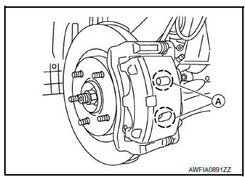
Wear thickness : Refer to BR-55, "Front Disc Brake".
DISC BRAKE ROTOR
DISC BRAKE ROTOR : Inspection
APPEARANCE
Check surface of disc brake rotor for uneven wear, cracks or damage. Replace if any abnormal conditions exist.
RUNOUT
- Check the wheel bearing axial end play before the inspection. Refer to FAX-7, "Inspection"(FWD) or FAX- 38, "Inspection"(AWD).
- Secure the disc brake rotor to the wheel hub and bearing with wheel nuts at two wheel nut locations.
- Inspect the runout with a dial gauge, measured at 10 mm (0.39 in) inside the disc brake rotor edge.
Runout : Refer to BR-55, "Front Disc Brake".
- Find the installation position with a minimum runout by shifting the disc brake rotor-to-wheel hub and bearing installation position by one hole at a time if the runout exceeds the limit value.
- Refinish the disc brake rotor if the runout is outside the limit even after performing the above operation. When refinishing, use Tool.
Tool number : 38-PFM92
CAUTION:
- Check in advance that the thickness of the disc brake rotor is wear thickness + 0.3 mm (0.012 in) or more.
- If the thickness is less than wear thickness + 0.3 mm (0.012 in), replace the disc brake rotor.
Wear thickness : Refer to BR-55, "Front Disc Brake".
THICKNESS
Check the thickness of the disc brake rotor using a micrometer.
Replace the disc brake rotor if the thickness is below the wear limit.
Wear thickness : Refer to BR-55, "Front Disc
Brake".
Thickness variation : Refer to BR-55, "Front Disc
Brake".
 Brake booster
Inspection
Operation
Depress the brake pedal several times at five second intervals with
the engine stopped. Start the engine with the brake pedal fully
depressed. Check that the clearance between ...
 Rear disc brake
BRAKE PAD
BRAKE PAD : Inspection
INSPECTION
Check brake pad wear thickness from an inspection hole (A) on cylinder
body. Check using a scale if necessary.
Wear thickness : Refer to BR-55, &qu ...
Other materials:
Starting the engine (models without NISSAN
Intelligent Key® system)
Apply the parking brake.
Move the shift lever to P (Park) or N (Neutral).
P (Park) is recommended.
The shift lever cannot be moved out of
P (Park) and into any of the other gear
positions if the ignition key is turned to
the OFF position or if the key is removed
from the ignition ...
Front wiper does not operate
Description
The front wiper does not operate under any operation conditions.
Diagnosis Procedure
Regarding Wiring Diagram information, refer to WW-22, "Wiring Diagram".
1. CHECK WIPER RELAY OPERATION
CONSULT ACTIVE TEST
Select FR WIPER of BCM (WIPER) active test item.
&nb ...
Interior room lamp power supply circuit
Description
Provides the interior room lamp power supply. Also cuts the power supply when
the interior room lamp battery
saver is activating.
Component Function Check
1.CHECK INTERIOR ROOM LAMP POWER SUPPLY FUNCTION
CONSULT ACTIVE TEST
Turn power switch ON.
Turn each interio ...
