Nissan Rogue Service Manual: ECU diagnosis information
DIAGNOSIS SENSOR UNIT
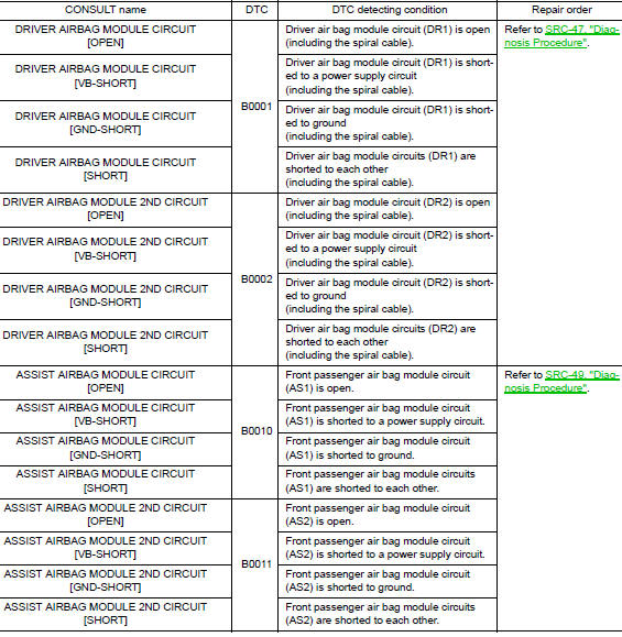
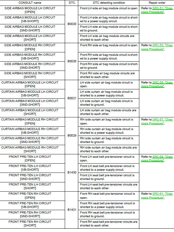
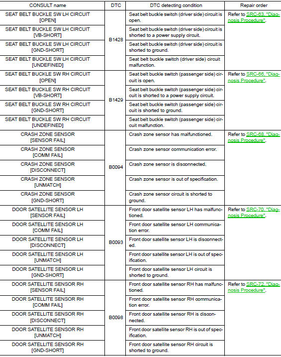
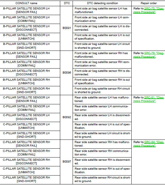
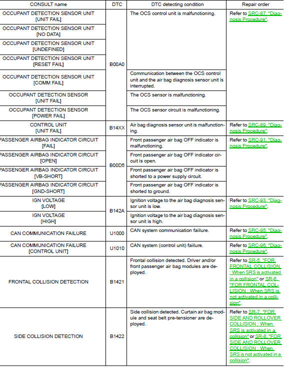
DTC Index
DIAGNOSTIC CODE CHART
NOTE: Follow the procedures in numerical order when repairing malfunctioning parts. Confirm whether malfunction is eliminated using air bag warning lamp or CONSULT each time repair is finished. If malfunction is still observed, proceed to the next step. When malfunction is eliminated, further repair work is not required.
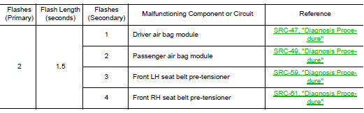
Flash Code Index
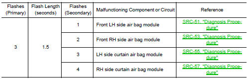
WARNING LAMP FLASH CODE CHART
- Put the vehicle in Diagnosis Mode. Refer to SRC-16, "On Board Diagnosis Function".
- All codes are proceded by a seven second "holding" flash.
- Identify how many primary flashes are displayed as well as the length of each primary flash.
- Refer to the tables and examples below to determine which SRS subsystem the code belongs to.
- Count the short secondary flashes that follow the primary flashes.
- Match the correct flashing pattern to the malfunctioning component and perform the Diagnosis Procedure.
Refer to the illustrations below for an example of each flashing pattern.
Front subsystem
Side subsystem
Air bag subsystem
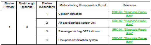
Sensor subsystem

 Diagnosis system (air bag)
Description
CAUTION:
Never use electrical test equipment on any circuit related to
the SRS unless instructed in this Service
Manual. SRS wiring harnesses can be identified by yellow an ...
 Wiring diagram
SRS AIR BAG SYSTEM
Wiring Diagram
...
Other materials:
Removal and installation
EXHAUST SYSTEM
Exploded View
Exhaust diffuser
Muffler assembly
Mounting rubber
Mounting rubber
Mounting rubber
Ring gasket
Front exhaust tube
Mounting rubber
Exhaust gasket
Oxygen sensor 2
Center exhaust tube
Catalyst shroud
...
Unit removal and installation
TRANSFER ASSEMBLY
Exploded View
1 Transfer assembly
: N·m (kg-m, ft-lb)
*: Apply anti-corrosion oil.
Removal and Installation
NOTE:
When removing components such as hoses, tubes/lines, etc., cap or plug openings
to prevent fluid from spilling.
REMOVAL
Remove front drive shaf ...
Front regulator
Exploded View
Front door panel
Front door regulator
Front door power window motor
Front door glass run rear
Front door glass run front
Front door glass
Front door glass rubber run
Removal and Installation
REMOVAL
Remove the front door finisher. Refer to INT-15, ...
