Nissan Rogue Service Manual: Removal and installation
DRIVE PINION OIL SEAL
Exploded View
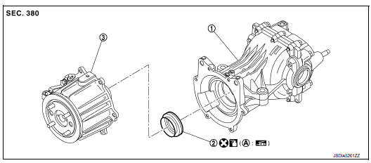
- Rear final drive assembly
- Drive pinion oil seal
- Electric controlled coupling assembly
- Oil seal lip
 Always replace after every
disassembly.
Always replace after every
disassembly.
 : Apply gear oil.
 : Apply multi-purpose grease.
Removal and Installation
REMOVAL
- Remove electric controlled coupling. Refer to DLN-114, "Removal and Installation".
- Using a suitable tool remove drive pinion oil seal.
CAUTION: Do not damage rear final drive assembly.
INSTALLATION
- Install drive pinon oil seal (1) using Tool (A).
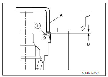
Oil seal installation
length (B)
: 0.8 - 1.2 mm (0.031 - 0.047 in)
Tool number : KV38100200 (J-26233)
: ST27861000 ( — )
CAUTION:
- Do not reuse oil seal.
- When installing, do not incline oil seal.
- Apply multi-purpose grease onto oil seal lips, and gear oil onto the circumference of oil seal.
- Install rear propeller shaft. Refer to DLN-99, "Exploded View".
- When oil leaks while removing, check oil level after the installation. Refer to DLN-111, "Inspection".
SIDE OIL SEAL
Exploded View
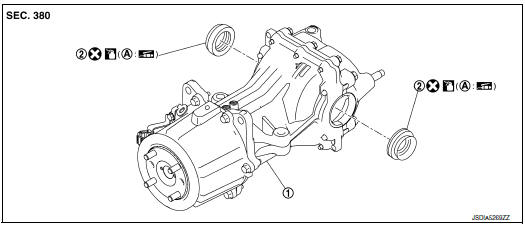
- Rear final drive assembly
- Side oil seal
- Oil seal lip
 : Always replace after every
disassembly.
: Always replace after every
disassembly.
 : Apply gear oil.
 : Apply multi-purpose grease.
Removal and Installation
REMOVAL
- Remove rear drive shaft (LH/RH) with power tool. Refer to RAX-19, "Exploded View".
- Remove side oil seal (LH/RH), using a suitable tool.
CAUTION: Do not damage gear carrier and rear cover.
INSTALLATION
- Install side oil seals until it becomes flush with the carrier end, using Tool (A).
Tool number : KV38100200 (J-26233)
CAUTION:
- Do not reuse oil seals.
- When installing, do not incline oil seals.
- Apply multi-purpose grease onto oil seal lips, and gear oil onto the circumference of oil seal.
- Install rear drive shafts. Refer to RAX-19, "Exploded View".
- When oil leaks while removing, check oil level after the
installation.
Refer to DLN-111, "Inspection".
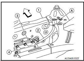
ELECTRIC CONTROLLED COUPLING
Exploded View
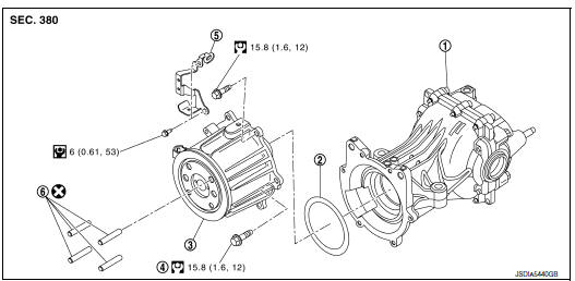
- Rear final drive assembly
- Wave spring
- Electric controlled coupling assembly
- Reamer bolt
- Connector bracket Stud bolt
 : N·m (kg-m, in-lb)
 : N·m (kg-m, ft-lb)
 : Always replace after every
disassembly.
: Always replace after every
disassembly.
Removal and Installation
NOTE: When removing components such as hoses, tubes/lines, etc., cap or plug openings to prevent fluid from spilling.
REMOVAL
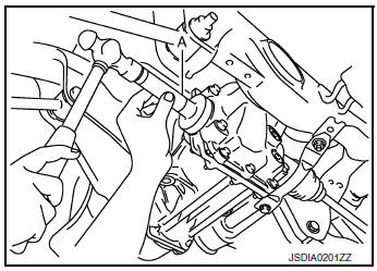
- Remove rear propeller shaft from the torsional damper, and support the end of the propeller shaft. Refer to DLN-99, "Exploded View".
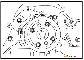
- Remove electric controlled coupling breather hose (2) from electric controlled coupling (1).
- Disconnect the electric controlled coupling harness connector (A).
- Remove harness connector bracket.
- Remove bolts from electric controlled coupling.
- Remove the electric controlled coupling.
CAUTION: Be careful that the wave washer does not fall out or get damaged when removing the electric controlled coupling.
- Remove wave washer (1).
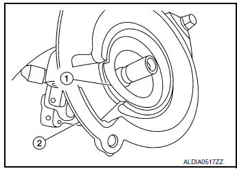
(2) : Rear final drive assembly
INSTALLATION
Installation is in the reverse order of removal.
CAUTION:
- Do not reuse hose clamp and breather connector.
- Make sure there are no pinched or restricted areas on the breather hose caused by bending or winding when installing it.
- Install the hose clamp at the final drive side, with the tab facing to the vehicle front.
- Install the hose clamp at the suspension member side, with the tab facing downward.
- Use Genuine Silicone RTV or an equivalent. Refer to GI-22, "Recommended Chemical Products and Sealants".
- Remove the old sealant from mating surfaces using a suitable tool before installing.
- Apply liquid gasket (1) to mating surface of coupling cover.
Use Genuine Silicone RTV or equivalent. Refer to GI-22, "Recommended Chemical Products and Sealants".
CAUTION:
- The width of sealant bend is approximately 3 mm (0.012 in).
- Installation should be done within 5 minutes after applying liquid gasket.
- Do not fill the engine within engine oil for at least 30 minutes after the components are installed to allow the sealant to cure.

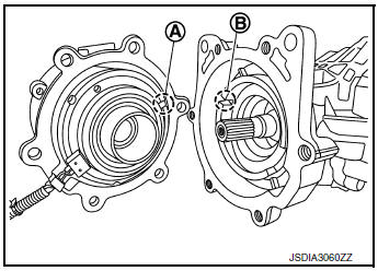
- Install electric controlled coupling to spline of drive pinion inside final drive assembly.
CAUTION:
- Align the pin (A) on electric controlled coupling with the groove (B) of final drive assembly.
- Be careful not to damage center oil seal.
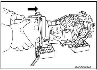
- Press the electric controlled coupling pin to check that it is
positioned
in the groove of the final drive assembly as shown.
NOTE: If the pin is properly positioned in the groove, then the electric controlled coupling can be pressed into position by the same amount of flection of the wave washer.
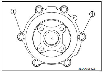
- Temporarily tighten reamer bolts (1) to the positions shown.
CAUTION:
- • Do not use tools. Always tighten by hand.
- • If reamer bolts cannot be tightened all the way by hand, the electric controlled coupling pin may not be positioned in the groove of the final drive assembly. In this case, remove electric controlled coupling and reinstall it.
- When oil leaks while removing, check oil level after the installation. Refer to DLN-111, "Inspection".
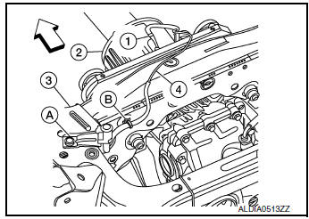
AIR BREATHER
Exploded View
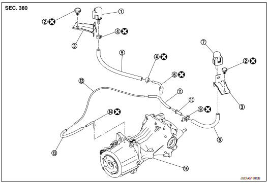
- Breather connector (resin)
- Trim clip
- Bracket
- Hose clamp
- Air breather hose
- Breather connector (metal)
- Breather connector (resin)
- Air breather hose
- Clip
- Hose connector
- Air breather hose*
- Air breather tube*
- Air breather hose*
- Breather connector (metal)
- Rear final drive assembly
 : Always replace after every
disassembly.
: Always replace after every
disassembly.
*: These parts are adhered to each other. Therefore they are assembled parts.
Removal and Installation
- REMOVAL Remove clip (A) from rear suspension member (1).
(3) : Rear final drive assembly
 : Front
- Remove air breather hose (2) and breather tube (4) together.
- Loosen hose clamp and remove breather tube from air breather hose.
- Remove clips (A) from rear suspension member (3).
(2) : Rear final drive assembly
: Front
INSTALLATION
Installation is in the reverse order of removal.
- For non-reusable parts, refer to DLN-117, "Exploded View".
- Set breather connector (1) to rear final drive with the paint mark (A) facing front as shown.
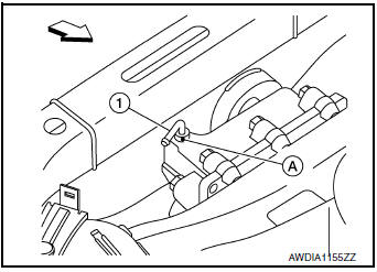
: Front
- When installing air breather hose, make sure there are no pinched or restricted areas on air breather hose caused by bending or winding.
 Periodic maintenance
REAR DIFFERENTIAL GEAR OIL
Inspection
OIL LEAKS
Make sure that oil is not leaking from final drive assembly or around it.
OIL LEVEL
Remove filler plug (1) and check oil level from filler ...
 Unit removal and installation
REAR FINAL DRIVE ASSEMBLY
Exploded View
Final drive mounting bracket
Mounting stopper
Rear final drive assembly
: N·m (kg-m, ft-lb)
: Always replace after every
disassembly.
Rem ...
Other materials:
P0139 HO2S2
DTC Description
DTC DETECTION LOGIC
The heated oxygen sensor 2 has a much longer switching time
between rich and lean than the air fuel ratio (A/F) sensor 1. The oxygen
storage capacity of the three way catalyst 1 causes the longer
switching time. To judge the malfunctions of heated oxygen sens ...
Component parts
Component Parts Location
View of cowl area (with cowl top cover
removed)
RH front of vehicle (with front
bumper fascia removed)
View with back door finisher removed
No.
Component
Function
1
Combination switch
(Wiper and washer switch)
Ref ...
System description
COMPONENT PARTS
Component Parts Location
No.
Component
Description
1
Push-button ignition
switch1
Push-button ignition switch (push switch) is pressed (ON), and
transmits status signal to BCM
and IPDM E/R.
Ignition switch2
Ignition ...
