Nissan Rogue Service Manual: DTC/circuit diagnosis
U1000 CAN COMM CIRCUIT
Description
Refer to LAN-8, "System Description".
DTC Logic
DTC DETECTION LOGIC
NOTE: U1000 can be set if a module harness was disconnected and reconnected, perhaps during a repair. Confirm that there are actual CAN diagnostic symptoms and a present DTC by performing the Self Diagnostic Result procedure.
|
CONSULT Display |
DTC Detection Condition |
Possible cause |
| CAN COMM CIRCUIT [U1000] | When any listed module cannot communicate with CAN communication signal continuously for 2 seconds or more with ignition switch ON. | In CAN communication system, any item (or items)
of the following listed below is malfunctioning.
|
Diagnosis Procedure
1. PERFORM SELF DIAGNOSTIC
- Turn ignition switch ON and wait for 2 second or more.
- Check “SELF- DIAG RESULTS”.
Is “CAN COMM CIRCUIT” displayed? YES >> Perform CAN Diagnosis as described in DIAGNOSIS section of CONSULT Operation Manual.
NO >> Refer to GI-41, "Intermittent Incident".
U1010 CONTROL UNIT (CAN)
DTC Logic
DTC DETECTION LOGIC
|
DTC DETECTION LOGIC |
DTC Detection Condition |
DTC Detection Condition |
| CAN COMM CIRCUIT [U1010] | BCM detected internal CAN communication circuit malfunction. | BCM detected internal CAN communication circuit malfunction. |
Diagnosis Procedure
1. REPLACE BCM
When DTC U1010 is detected, replace BCM.
>> Replace BCM. Refer to BCS-135, "Removal and Installation".
U0415 VEHICLE SPEED SIG
Description
U0415 is displayed if any unusual condition is present in the reception status of the vehicle speed signal from the ABS actuator and electric unit (control unit).
DTC Logic
DTC DETECTION LOGIC
NOTE:
- If DTC U0415 is displayed with DTC U1000, first perform the trouble diagnosis for DTC U1000. Refer to BCS-124, "DTC Logic".
- If DTC U0415 is displayed with DTC U1010, first perform the trouble diagnosis for DTC U1010. Refer to BCS-125, "DTC Logic".
|
CONSULT Display |
DTC Detection Condition |
Possible Cause |
| VEHICLE SPEED SIG [U0415] | When the vehicle speed signal received from the ABS actuator and electric unit (control unit) remains abnormal for 2 seconds or more. |
|
DTC CONFIRMATION PROCEDURE
1. DTC CONFIRMATION
- Erase the DTC.
- Turn ignition switch OFF.
- Perform Self Diagnostic Result of BCM with CONSULT, after the ignition switch has been turned ON for 2 seconds or more.
Is any DTC detected? YES >> Refer to BCS-108, "DTC Index".
NO >> Inspection End.
Diagnosis Procedure
1. ABS ACTUATOR AND ELECTRIC UNIT (CONTROL UNIT) SELF DIAGNOSTIC RESULT
Perform Self Diagnostic Result of ABS with CONSULT. Refer to BRC-44, "CONSULT Function".
Is any DTC detected? YES >> Perform the trouble diagnosis related to the detected DTC. Refer to BRC-55, "DTC Index".
NO >> GO TO 2.
2. CHECK ABS ACTUATOR AND ELECTRIC UNIT (CONTROL UNIT) POWER SUPPLY AND GROUND CIRCUIT
Check ABS actuator and electric unit (control unit) power and ground. Refer to BRC-80, "Diagnosis Procedure".
Is the inspection result normal? YES >> GO TO 3.
NO >> Repair or replace harness or connectors.
3. COMBINATION METER SELF DIAGNOSTIC RESULT
Perform Self Diagnostic Result of METER M&A with CONSULT. Refer to MWI-21, "CONSULT Function (METER/M&A)".
Is any DTC detected? YES >> Perform the trouble diagnosis related to the detected DTC. Refer to MWI-30, "DTC Index".
NO >> Refer to GI-41, "Intermittent Incident".
B2562 LOW VOLTAGE
DTC Logic
DTC DETECTION LOGIC
|
CONSULT Display |
DTC Detection Condition |
Possible cause |
| LOW VOLTAGE [B2562] | When the power supply voltage to BCM remains less than 8.8V for 120 seconds or more. |
|
DTC CONFIRMATION PROCEDURE
1. DTC CONFIRMATION
- Erase DTC.
- Turn ignition switch OFF.
- Perform the Self Diagnostic Result of BCM with CONSULT, after the ignition switch has been turned ON for 120 seconds or more.
Is any DTC detected? YES >> Refer to BCS-127, "Diagnosis Procedure".
NO >> Inspection End.
Diagnosis Procedure
1. CHECK BATTERY VOLTAGE
Check battery voltage.
Is battery voltage less than 8.8V? YES >> Charge battery and retest. Refer to CHG-11, "Work Flow (With EXP-800 NI or GR8-1200 NI)" or CHG-14, "Work Flow (Without EXP-800 NI or GR8-1200 NI)".
NO >> GO TO 2.
2. CHECK POWER SUPPLY AND GROUND CIRCUIT
Check BCM power supply and ground circuit. Refer to BCS-128, "Diagnosis Procedure".
Is the inspection result normal? YES >> GO TO 3.
NO >> Repair or replace harness or connectors.
3. BCM SELF DIAGNOSTIC RESULT
Perform Self Diagnostic Result of BCM with CONSULT. Refer to BCS-92, "BCM : CONSULT Function (BCM - BCM)".
Is DTC B2562 CRNT? YES >> Replace BCM. Refer to BCS-135, "Removal and Installation".
NO >> Refer to GI-41, "Intermittent Incident".
POWER SUPPLY AND GROUND CIRCUIT
Diagnosis Procedure
Regarding Wiring Diagram information, refer to BCS-110, "Wiring Diagram".
1. CHECK FUSE
Check that the following fuse is not blown.

Is the fuse blown? YES >> Replace the blown fuse after repairing the affected circuit.
NO >> GO TO 2.
2. CHECK POWER SUPPLY CIRCUIT
- Disconnect BCM connector M20.
- Check voltage between BCM connector M20 and ground.
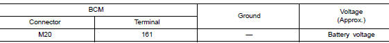
Is the inspection result normal? YES >> GO TO 3.
NO >> Repair or replace harness or connectors.
3. CHECK GROUND CIRCUIT
Check continuity between BCM connector M20 and ground.
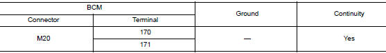
Is the inspection result normal? YES >> Inspection End.
NO >> Repair or replace harness or connectors.
COMBINATION SWITCH INPUT CIRCUIT
Diagnosis Procedure
Regarding Wiring Diagram information, refer to BCS-110, "Wiring Diagram".
1. CHECK INPUT 1 - 5 SYSTEM CIRCUIT FOR OPEN
- Turn ignition switch OFF.
- Disconnect BCM connector M18 and combination switch connector.
- Check continuity between BCM connector M18 and combination switch connector M28.
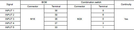
Is the inspection result normal? YES >> GO TO 2.
NO >> Repair or replace harness or connectors.
2. CHECK INPUT 1 - 5 SYSTEM CIRCUIT FOR SHORT
Check continuity between BCM connector M18 and ground.
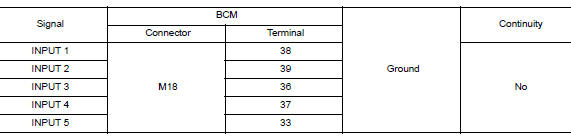
Is the inspection result normal? YES >> GO TO 2.
NO >> Repair or replace harness or connectors.
2. CHECK INPUT 1 - 5 SYSTEM CIRCUIT FOR SHORT
Check continuity between BCM connector M18 and ground.
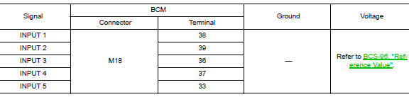
Is the inspection result normal? YES >> Replace the combination switch. Refer to BCS-136, "Removal and Installation".
NO >> Replace BCM. Refer to BCS-135, "Removal and Installation".
COMBINATION SWITCH OUTPUT CIRCUIT
Diagnosis Procedure
Regarding Wiring Diagram information, refer to BCS-110, "Wiring Diagram".
1. CHECK OUTPUT 1 - 5 SYSTEM CIRCUIT FOR OPEN
- Turn ignition switch OFF.
- Disconnect BCM connector M19 and combination switch connector.
- Check continuity between BCM connector M19 and combination switch connector M28.
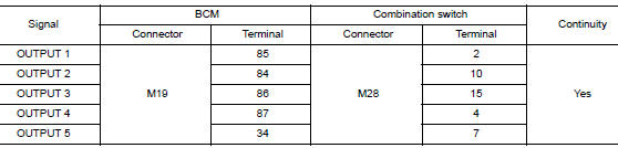
Is the inspection result normal? YES >> GO TO 2.
NO >> Repair or replace harness or connectors.
2. CHECK OUTPUT 1 - 5 SYSTEM CIRCUIT FOR SHORT
Check continuity between BCM connector M19 and ground.
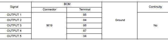
Is the inspection result normal? YES >> GO TO 3.
NO >> Repair or replace harness or connectors.
3. CHECK BCM INPUT VOLTAGE
- Connect BCM connector M19 and combination switch connector.
- Turn ignition switch ON.
- Check voltage between BCM connector M19 and ground.
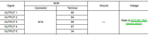
Is the inspection result normal? YES >> Replace BCM. Refer to BCS-135, "Removal and Installation".
NO >> Replace the combination switch. Refer to BCS-136, "Removal and Installation".
 Basic inspection
INSPECTION AND ADJUSTMENT
ADDITIONAL SERVICE WHEN REPLACING CONTROL UNIT (BCM)
ADDITIONAL SERVICE WHEN REPLACING CONTROL UNIT (BCM) : Description
BEFORE REPLACEMENT
When replacing BCM, save or pri ...
 Symptom diagnosis
COMBINATION SWITCH SYSTEM SYMPTOMS
Symptom Table
Perform the data monitor of CONSULT to check for any malfunctioning
item.
Check the malfunction combinations.
Identify the ma ...
Other materials:
Replacement operations
Description
This section is prepared for technicians who have attained a high level
of skill and experience in repairing
collision-damaged vehicles and also use modern service tools and equipment.
Persons unfamiliar with body
repair techniques should not attempt to repair collision-dam ...
P0078 EVT control solenoid valve
DTC Description
DTC DETECTION LOGIC
DTC No.
CONSULT screen terms
(Trouble diagnosis content)
DTC detecting condit
P0078
EX V/T ACT/CIRC-B1
(Exhaust valve control solenoid circuit bank
1)
An improper voltage is sent to the ECM through exhaust valve timing
co ...
Fuel injector and fuel tube
Exploded View
Rocker cover
Cylinder head
Fuel tube
Clip
O-ring (green)
Fuel injector
O-ring (black)
Front
Removal and Installation
WARNING:
Put a "CAUTION: FLAMMABLE" sign in the workshop.
Be sure to work in a well ve ...
