Nissan Rogue Service Manual: Differential side oil seal
Exploded View
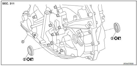
- Transaxle assembly
- Differential side oil seal (left side)
- Differential side oil seal (right side) (FWD models only)
 : Always replace after every
disassembly.
: Always replace after every
disassembly.
 : Apply CVT fluid
Removal and Installation
REMOVAL
NOTE: When removing components such as hoses, tubes/lines, etc., cap or plug openings to prevent fluid from spilling.
- Remove front drive shaft. Refer to FAX-18, "Removal and Installation (LH)" (FWD) or FAX-50, "Removal and Installation (LH)" [LH (AWD)]or FAX-52, "Removal and Installation (RH)" [RH(AWD)].
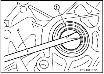
- Remove differential side oil seal (1) using suitable tool (A).
CAUTION: Be careful not to scratch transaxle case and converter housing.
INSTALLATION
Installation is in the reverse order of removal.
CAUTION:
- Do not reuse differential side oil seal.
- Apply CVT fluid to differential side oil seals.
- When inserting the drive shaft, be sure to use Tool.
Tool number: KV38107900
Install each differential side oil seal evenly using suitable tool so that differential side oil seal protrudes by the dimension (C) and (D) respectfully.

(A) : Differential side oil seal (LH)
(B) : Differential side oil seal (RH) (FWD models only)
Dimension (C) :Height difference from case end surface is within 1.8 ± 0.5 mm (0.071 ± 0.020 in).
Dimension (D) :Height difference from case end surface is within 2.2 ± 0.5 mm (0.087 ± 0.020 in).
NOTE: The reference is the installation direction of the differential side oil seal.
Drift to be used:
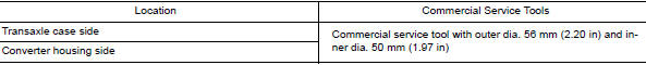
Inspection and Adjustment
INSPECTION AFTER INSTALLATION
Check for CVT fluid leakage. Refer to TM-190, "Inspection".
ADJUSTMENT AFTER INSTALLATION
Adjust the CVT fluid level. Refer to TM-192, "Adjustment".
 Output speed sensor
Exploded View
Transaxle assembly
Output speed sensor
O-ring
Always replace after every
disassembly.
: N·m (kg-m, in-lb)
: Apply CVT fluid
Removal and Installation
REMOVAL
...
 Water hose
Exploded View
Water outlet
Hose clamp
Water hose A
Clip
CVT oil warmer
Transaxle assembly
Water hose B
Heater thermostat
Water hose C
: Always replace after every
di ...
Other materials:
Tilt/telescopic steering
WARNING
Do not adjust the steering wheel while
driving. You could lose control of your
vehicle and cause an accident.
Do not adjust the steering wheel any
closer to you than is necessary for
proper steering operation and comfort.
The driver’s air bag ...
Daytime running light system
The daytime running lights automatically illuminate
when the engine is started with the parking
brake released. The daytime running lights operate
with the headlight switch in the OFF position
or in the position. Turn the
headlight switch
to the position for full
illumination when
drivin ...
System description
COMPONENT PARTS
Component Parts Location
No.
Component
Description
1
Push-button ignition
switch1
Push-button ignition switch (push switch) is pressed (ON), and
transmits status signal to BCM
and IPDM E/R.
Ignition switch2
Ignition ...
