Nissan Rogue Service Manual: Diagnosis system [ABS actuator and electric unit (control unit)]
CONSULT Function
APPLICATION ITEMS
CONSULT can display each diagnostic item using the diagnostic test modes as follows.
|
Mode |
Function description |
| ECU identification | Parts number of ABS actuator and electric unit (control unit) can be read. |
| Self Diagnostic Result | Self-diagnostic results and freeze frame data can be read and erased quickly.* |
| DATA MONITOR | Input/Output data in the ABS actuator and electric unit (control unit) can be read. |
| ACTIVE TEST | Input/Output data in the ABS actuator and electric unit (control unit) can be read. |
| WORK SUPPORT | Components can be quickly and accurately adjusted. |
| Re/programming, Configuration |
|
*: The following diagnosis information is erased by erasing.
- DTC
- Freeze frame data (FFD)
ECU IDENTIFICATION
ABS actuator and electric unit (control unit) part number can be read.
SELF DIAGNOSTIC RESULT
Refer to BRC-55, "DTC Index".
When ÔÇťCRNTÔÇŁ is displayed on self-diagnosis result,
- The system is presently malfunctioning.
When ÔÇťPASTÔÇŁ is displayed on self-diagnosis result,
- System malfunction in the past is detected, but the system is presently normal.
Freeze frame data (FFD)
The following vehicle status is recorded when DTC is detected and is displayed on CONSULT.
|
Item name |
Display item |
| IGN counter (0 Ôłĺ 39) | The number of times that ignition switch is turned ON after the DTC
is detected is displayed.
NOTE: Each time when ignition switch is turned OFF to ON, numerical number increases in 1 Ôćĺ 2 Ôćĺ 3...38 Ôćĺ 39. When the operation number of times exceeds 39, the number do not increase and ÔÇť39ÔÇŁ is displayed until self-diagnosis is erased. |
ACTIVE TEST
The active test is used to determine and identify details of a malfunction, based on self-diagnosis test results and data obtained in the DATA MONITOR. In response to instructions from CONSULT, instead of those from ABS actuator and electric unit (control unit) on the vehicle, a drive signal is sent to the actuator to check its operation.
CAUTION:
- Never perform ACTIVE TEST while driving the vehicle.
- Always bleed air from brake system before active test.
- Never perform active test when system is malfunctioning.
NOTE:
- When active test is performed while depressing the pedal, the pedal depressing stroke may change. This is not a malfunction.
- ÔÇťTEST IS STOPPEDÔÇŁ is displayed approx. 10 seconds after operation start.
- When performing active test again after ÔÇťTEST IS STOPPEDÔÇŁ is displayed, select ÔÇťBACKÔÇŁ.
- ABS warning lamp, brake warning lamp and VDC warning lamp may turn ON during active test. This is not a malfunction.
ABS IN Valve and ABS OUT Valve
When ÔÇťUpÔÇŁ, ÔÇťKeepÔÇŁ or ÔÇťDownÔÇŁ is selected on display screen, the following items are displayed when system is normal.
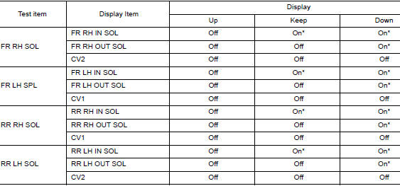
*: Immediately after being selected, status is ÔÇťOnÔÇŁ. Status changes to ÔÇťOffÔÇŁ after approx. 2 seconds.
ABS IN Valve (ACT) and ABS OUT Valve (ACT)
When ÔÇťUpÔÇŁ, ÔÇťACT UPÔÇŁ or ÔÇťACT KEEPÔÇŁ is selected on display screen, the following items are displayed when system is normal.
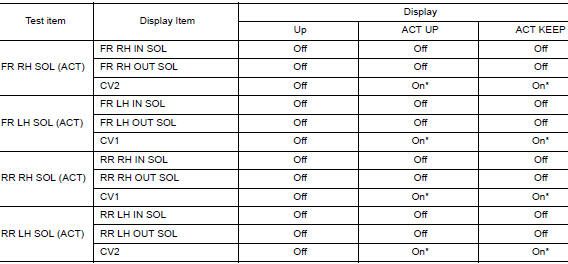
*: Immediately after being selected, status is ÔÇťOnÔÇŁ. Status changes to ÔÇťOffÔÇŁ after approx. 10 seconds.
ABS MOTOR
When ÔÇťOnÔÇŁ or ÔÇťOffÔÇŁ is selected on display screen, the following items are displayed when system is normal.
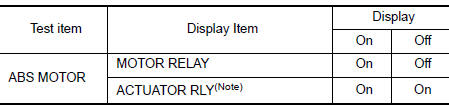
NOTE: Display occasionally changes On/Off for a moment after ignition switch is turned ON. This is operation for checking purposes and is not a malfunction.
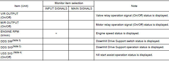
DATA MONITOR
NOTE: The following table includes information (items) inapplicable to this vehicle. For information (items) applicable to this vehicle, refer to CONSULT display items.
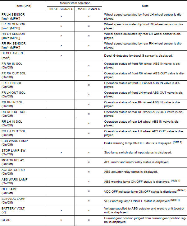
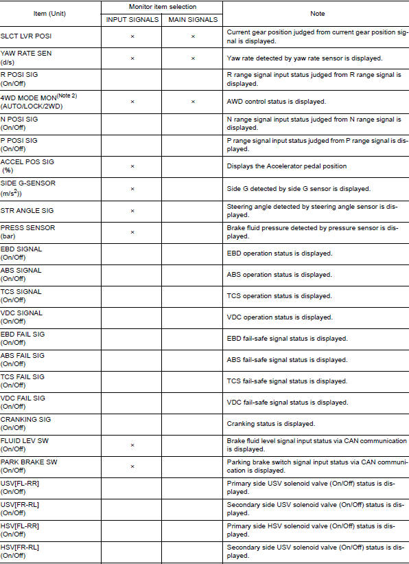
Note 1: Refer to BRC-14, "System Description" for ON/OFF conditions of each
warning lamp and indicator
lamp.
Note 2: AWD models
Note 3: DDSÔÇŁ (Downhill Drive Support)
Note 4: USS (Hill Start Assist)
WORK SUPPORT
|
Conditions |
Description |
| ST ANGLE SENSOR ADJUSTMENT | Perform neutral position adjustment of steering angle sensor |
| DECEL G SEN CALIBRATION | Perform decel G sensor calibration. |
 System
System Description
The system switches fluid pressure of each brake caliper to increase, to
hold or to decrease according to
signals from control unit in ABS actuator and electric unit (contr ...
 ECU diagnosis information
ABS ACTUATOR AND ELECTRIC UNIT (CONTROL UNIT)
Reference Value
CONSULT DATA MONITOR STANDARD VALUE
NOTE:
The following table includes information (items) inapplicable to this vehicle.
For informa ...
Other materials:
Basic inspection
DIAGNOSIS AND REPAIR WORKFLOW
Workflow
OVERALL SEQUENCE
DETAILED FLOW
1.INTERVIEW CUSTOMER
Interview the customer to obtain as much information as possible about the
conditions and environment under
which the malfunction occurred.
>> GO TO 2.
2.SYMPTOM CHECK
Verify symptoms.
...
Precaution
Precaution for Supplemental Restraint System (SRS) "AIR BAG" and "SEAT
BELT
PRE-TENSIONER"
The Supplemental Restraint System such as ÔÇťAIR BAGÔÇŁ and ÔÇťSEAT BELT PRE-TENSIONERÔÇŁ,
used along
with a front seat belt, helps to reduce the risk or severity of injury to the
...
Precaution
Precaution for Supplemental Restraint System (SRS) "AIR BAG" and "SEAT
BELT
PRE-TENSIONER"
The Supplemental Restraint System such as ÔÇťAIR BAGÔÇŁ and ÔÇťSEAT BELT
PRE-TENSIONERÔÇŁ, used along
with a front seat belt, helps to reduce the risk or severity of injury to the
...
