Nissan Rogue Service Manual: C119A vacuum sensor
DTC Logic
DTC DETECTION LOGIC
| DTC | Display Item | Malfunction detected condition | Possible causes |
| C119A | VACUUM SEN VOLT | When a malfunction is detected in supply power voltage of vacuum sensor. |
|
DTC CONFIRMATION PROCEDURE
1.CHECK SELF-DIAGNOSTIC RESULT
 With CONSULT.
- Turn the ignition switch ON.
- Perform self-diagnostic result.
Is DTC C119A detected? YES >> Proceed to diagnosis procedure. Refer to BRC-111, "Diagnosis Procedure".
NO >> Inspection End.
Diagnosis Procedure
Regarding Wiring Diagram information, refer to BRC-57, "Wiring Diagram".
1.CHECK VACUUM SENSOR POWER SUPPLY
- Turn the ignition switch OFF.
- Disconnect vacuum sensor harness connector.
- Check voltage between vacuum sensor harness connector and ground.
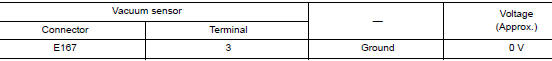
- Turn the ignition switch ON.
CAUTION: Never start engine.
- Check voltage between vacuum sensor harness connector and ground.
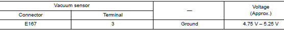
Is the inspection result normal? YES >> GO TO 3.
NO >> GO TO 2.
2.CHECK VACUUM SENSOR POWER SUPPLY CIRCUIT
- Turn the ignition switch OFF.
- Disconnect ABS actuator and electric unit (control unit) harness connector.
- Check continuity between vacuum sensor harness connector and ABS actuator and electric unit (control unit) harness connector.
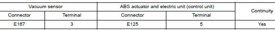
- Check continuity between vacuum sensor harness connector and ground.
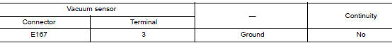
Is the inspection result normal? YES >> Perform diagnosis of ABS actuator and electric unit (control unit) power supply and ground circuit.
Refer to BRC-111, "Diagnosis Procedure".
NO >> Repair or replace malfunctioning components.
3.CHECK VACUUM SENSOR GROUND CIRCUIT
- Turn the ignition switch OFF.
- Check continuity between vacuum sensor harness connector and ground.
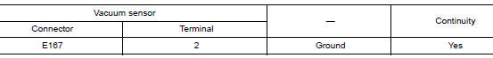
Is the inspection result normal? YES >> GO TO 4.
NO >> Repair or replace malfunctioning components.
4.CHECK TERMINAL
- Check vacuum sensor pin terminals for damage or loose connection with harness connector.
- Check ABS actuator and electric unit (control unit) pin terminals for damage or loose connection with harness connector.
Is the inspection result normal? YES >> Replace ABS actuator and electric unit (control unit). Refer to BRC-136, "Removal and Installation".
NO >> Repair or replace malfunctioning components.
 C1199 brake booster
DTC Logic
DTC DETECTION LOGIC
DTC
Display Item
Malfunction detected condition
Possible causes
C1199
BRAKE BOOSTER
When brake booster vacuum is approx. 0 kPa (0 mm-
...
 U1000 CAN COMM CIRCUIT
Description
CAN communication allows a high rate of information transmission through the
two communication lines
(CAN-H line and CAN-L line) connecting various control units in the system. Each
...
Other materials:
FM/AM radio with compact disc (CD) player
(if so equipped)
FM/AM radio with compact disc (CD) player
CD eject button
CD button
Display screen
CD insert slot
SEEK button
SCAN button
TRACK button
BACK button
iPod MENU button
TUNE/FOLDER knob, ENTER/SETTING
button
Sta ...
Warning/indicator lights
Warning
light
Name
Anti-lock Braking
System (ABS) warning
light
Brake warning light
Charge warning
light
Low tire pressure
warning light
Low windshield
washer fluid warning
light
Master w ...
Valve timing control
Exploded View
Valve timing cover
2. O-rings
Intake valve timing intermediate
lock control solenoid valve
Intake valve timing control solenoid
valve
Exhaust valve timing control solenoid
valve
Intake Valve Timing Intermediate Lock Control Solenoid Valve, Intake ...
