Nissan Rogue Service Manual: C1143 steering angle sensor
DTC Logic
DTC DETECTION LOGIC
| DTC | Display Item | Malfunction detected condition | Possible causes |
| C1143 | ST ANG SEN CIRCUIT | When a malfunction is detected in steering angle sensor. |
|
DTC CONFIRMATION PROCEDURE
1.CHECK SELF-DIAGNOSTIC RESULT
 With CONSULT.
- Turn ignition switch OFF to ON.
- Perform self-diagnostic result.
Is DTC C1143 detected? YES >> Proceed to diagnosis procedure. Refer to BRC-96, "Diagnosis Procedure".
NO >> Inspection End.
Diagnosis Procedure
Regarding Wiring Diagram information, refer to BRC-57, "Wiring Diagram".
1.CONNECTOR INSPECTION
- Turn ignition switch OFF.
- Disconnect ABS actuator and electric unit (control unit) and steering angle sensor connectors.
- Check connectors and terminals for deformation, disconnection, looseness or damage.
Is the inspection result normal? YES >> GO TO 2.
NO >> Repair or replace as necessary.
2.CHECK STEERING ANGLE SENSOR MOUNTING CONDITION
Check steering angle sensor mounting condition.
Is the inspection result normal? YES >> GO TO 3.
NO >> Repair or replace malfunctioning components.
3.CHECK STEERING ANGLE SENSOR POWER SUPPLY
- Turn ignition switch OFF.
- Disconnect steering angle sensor connector.
- Turn ignition switch ON.
- Check voltage between steering angle sensor connector M56 terminal 4 and ground.
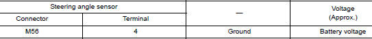
Is the inspection result normal? YES >> GO TO 5.
NO >> GO TO 4.
4.CHECK STEERING ANGLE SENSOR POWER SUPPLY CIRCUIT
- Turn ignition switch OFF.
- Disconnect fuse block (J/B) connector M44.
- Check continuity between steering angle sensor connector M56 terminal 4 and Fuse block (J/B) connector M44 terminal 7P.

- Check continuity between steering angle sensor connector M54 terminal 4 and ground.
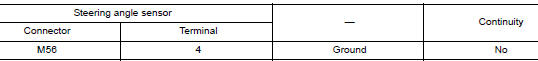
Is the inspection result normal? YES >> Perform trouble diagnosis for ignition power supply.
NO >> Repair or replace malfunctioning components.
5.CHECK STEERING ANGLE SENSOR GROUND CIRCUIT
- Turn ignition switch OFF.
- Check continuity between steering angle sensor connector M56 terminal 1 and ground.
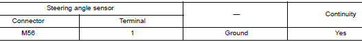
Is the inspection result normal? YES >> GO TO 6.
NO >> Repair or replace malfunctioning components.
6.CHECK CAN COMMUNICATION LINE
Check “STRG BRANCH LINE CIRCUIT”. Refer to LAN-90, "Diagnosis Procedure" (Type 1) or LAN-111, "Diagnosis Procedure" (Type 2).
Is the inspection result normal? YES >> Replace ABS actuator and electric unit (control unit). Refer to BRC-136, "Removal and Installation".
NO >> Repair or replace malfunctioning components.
 C1142 press sensor
DTC Logic
DTC DETECTION LOGIC
DTC
Display Item
Malfunction detected condition
Possible causes
C1142
PRESS SEN CIRCUIT
When a malfunction is detected in master cylinder ...
 C1144 incomplete steering angle sensor adjustment
DTC Logic
DTC DETECTION LOGIC
DTC
Display Item
Malfunction detected condition
Possible causes
C1144
ST ANG SEN SIGNAL
When neutral position adjustment of steering angl ...
Other materials:
Unit disassembly and assembly
REAR DRIVE SHAFT
Exploded View
DISASSEMBLY
Circular clip
Dust shield
Slide joint housing
Snap ring
Spider assembly
Boot band
Boot
Shaft
Circular clip
Joint sub-assembly
Sensor rotor
: Wheel side
Disassembly and Assembly
DISASSEMBLY
Final Dri ...
Basic inspection
DIAGNOSIS AND REPAIR WORK FLOW
Work Flow
OVERALL SEQUENCE
DETAILED FLOW
1.GET INFORMATION FOR SYMPTOM
Get detailed information from the customer about the symptom (the
condition and the environment when
the incident/malfunction occurs).
Check operation condition of the ...
C1730, C1731, C1732, C1733 flat tire
DTC Logic
NOTE:
The Signal Tech II Tool [- (J-50190)] can be used to perform the following
functions. Refer to the Signal Tech II
User Guide for additional information.
Activate and display TPMS sensor IDs
Display tire pressure reported by the TPMS sensor
Read TPMS DTC ...
