Nissan Rogue Service Manual: C1121, C1123, C1125, C1127 ABS out valve system
DTC Logic
DTC DETECTION LOGIC
| DTC | Display Item | Malfunction detected condition | Possible causes |
| C1121 | FR LH OUT ABS SOL | When a malfunction is detected in front LH ABS OUT valve. |
|
| C1123 | FR RH OUT ABS SOL | When a malfunction is detected in front RH ABS OUT valve. | |
| C1125 | RR LH OUT ABS SOL | When a malfunction is detected in rear LH ABS OUT valve. | |
| C1127 | RR RH OUT ABS SOL | When a malfunction is detected in rear RH ABS OUT valve. |
DTC CONFIRMATION PROCEDURE
1.CHECK SELF-DIAGNOSTIC RESULT
 With CONSULT.
- Turn ignition switch OFF to ON.
- Perform self-diagnostic result.
Is DTC C1121, C1123, C1125 or C1127 detected? YES >> Proceed to diagnosis procedure. Refer to BRC-89, "Diagnosis Procedure".
NO >> Inspection End.
Diagnosis Procedure
Regarding Wiring Diagram information, refer to BRC-57, "Wiring Diagram".
1.CONNECTOR INSPECTION
- Turn ignition switch OFF.
- Disconnect ABS actuator and electric unit (control unit) connectors.
- Check connectors and terminals for deformation, disconnection, looseness or damage.
Is the inspection result normal? YES >> GO TO 2.
NO >> Repair or replace as necessary.
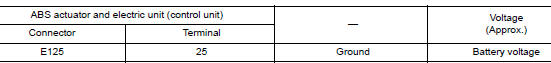
2.CHECK ABS ACTUATOR AND ELECTRIC UNIT (CONTROL UNIT) BATTERY POWER SUPPLY
Check voltage between ABS actuator and electric unit (control unit) connector E125 terminal 25 and ground.
Is the inspection result normal? YES >> GO TO 3.
NO >> Repair or replace malfunctioning components.
3.CHECK ABS ACTUATOR AND ELECTRIC UNIT (CONTROL UNIT) GROUND CIRCUIT
Check continuity between ABS actuator and electric unit (control unit) connector E125 terminals 13, 38 and ground.

Is the inspection result normal? YES >> Replace ABS actuator and electric unit (control unit). Refer to BRC-136, "Removal and Installation".
NO >> Repair or replace malfunctioning components.
 C1120, C1122, C1124, C1126 ABS in valve system
DTC Logic
DTC DETECTION LOGIC
DTC
Display Item
Malfunction detected condition
Possible causes
C1120
FR LH IN ABS SOL
When a malfunction is detected in front LH ABS IN
...
 C1130 engine signal
DTC Logic
DTC DETECTION LOGIC
DTC
Display Item
Malfunction detected condition
Possible causes
C1130
ENGINE SIGNAL 1
When a malfunction is detected in ECM system.
...
Other materials:
Symptom diagnosis
AUDIO SYSTEM
Symptom Table
RELATED TO AUDIO
Symptoms
Check items
Probable malfunction location
The disk cannot be removed
Audio unit
Malfunction in audio unit.
Refer to AV-18, "On Board Diagnosis Function".
No sound comes out or the le ...
DTC/circuit diagnosis
U0428 STEERING ANGLE SENSOR
DTC Logic
DTC DETECTION LOGIC
CONSULT Display
DTC Detection Condition
Possible Cause
ST ANG SEN CALIB
[U0428]
Predictive course line center position adjustment
of steering angle sensor is incomplete.
Adjust predictive cours ...
Sunglasses holder
Sunglasses holder
To open the sunglasses holder 1 , push and
release.
Only store one pair of sunglasses in the holder.
WARNINGKeep the sunglasses holder closed while
driving to prevent an accident.
CAUTION
Do not use for anything other than
sung ...
