Nissan Rogue Service Manual: Sensor power supply2 circuit
Description
ECM supplies a voltage of 5 V to some of the sensors systematically divided into 2 groups, respectively.
Accordingly, when a short circuit develops in a sensor power source, a malfunction may occur simultaneously in the sensors belonging to the same group as the short-circuited sensor.
Sensor power supply 1
- APP sensor 1
- CKP sensor (POS)
- Intake manifold runner control valve position sensor
- Refrigerant pressure sensor
- TP sensor
NOTE: If sensor power supply 1 circuit is malfunctioning, DTC P0643 is displayed.
Sensor power supply 2
- APP sensor 2
- CMP sensor (PHASE)
- EVT control position sensor
- EOP sensor
- MAF sensor
Diagnosis Procedure
1.CHECK APP SENSOR 2 POWER SUPPLY CIRCUIT-1
- Turn ignition switch OFF.
- Disconnect accelerator pedal position (APP) sensor harness connector.
- Turn ignition switch ON.
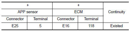
- Check the voltage between APP sensor harness connector and ground.

Is the inspection result normal? YES >> INSPECTION END
NO >> GO TO 2.
2.CHECK APP SENSOR 2 POWER SUPPLY CIRCUIT-2
- Turn ignition switch OFF.
- Disconnect ECM harness connector.
- Check the continuity between APP sensor harness connector and ECM harness connector.
Is the inspection result normal? YES >> GO TO 3.
NO >> Repair open circuit.
3.CHECK SENSOR POWER SUPPLY 2 CIRCUIT
- Disconnect following sensors harness connector.
- Check harness for short to power and short to ground, between the following terminals.
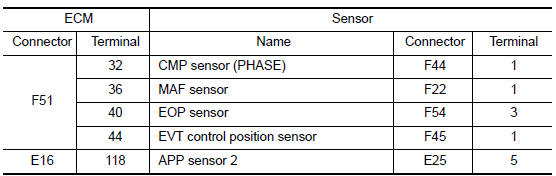
Is the inspection result normal? YES >> GO TO 4.
NO >> Repair short to ground or short to power in harness or connectors.
4.CHECK COMPONENTS
Check the following.
- APP sensor 2 (Refer to EC-444, "Component Inspection".)
- Camshaft position sensor (PHASE) (Refer to EC-300, "Component Inspection (Camshaft position sensor)".)
- EVT control position sensor (Refer to EC-387, "Component Inspection".)
- EOP sensor (Refer toEC-360, "Component Inspection".)
- MAF sensor (Refer to EC-200, "Component Inspection".)
Is the inspection result normal? YES >> Refer to GI-41, "Intermittent Incident".
NO >> Replace malfunctioning component.
 Refrigerant pressure sensor
Component Function Check
1.CHECK REFRIGERANT PRESSURE SENSOR FUNCTION
Start engine and warm it up to normal operating temperature.
Turn A/C switch and blower fan switch ON.
...

Other materials:
P0420 three way catalyst function
DTC Description
DTC DETECTION LOGIC
The ECM monitors the switching frequency ratio of air fuel ratio (A/F)
sensor 1 and heated oxygen sensor 2.
A three way catalyst (manifold) with high oxygen storage capacity
will indicate a low switching frequency of heated oxygen sensor 2.
As oxygen sto ...
Control buttons
Control buttons
The control buttons for the Bluetooth® Hands-
Free Phone System are located on the steering
wheel.
PHONE/SEND
Press the button to
initiate
a Voice Recognition session or
answer an incoming call.
You can also use the button
to interrupt the system feedback
and ...
U0073 communication bus a OFF
DTC Description
DTC DETECTION LOGIC
DTC
CONSULT screen terms
(Trouble diagnosis content)
DTC detection condition
U0073
COMM BUS A OFF
(Control Module Communication Bus A Off)
TCM communication blockage lasts for 2 seconds or more when turning
ON the ignition sw ...
