Nissan Rogue Service Manual: C1115 ABS sensor [abnormal signal]
DTC Logic
DTC DETECTION LOGIC
| DTC | Display Item | Malfunction detected condition | Possible causes |
| C1115 | ABS SENSOR [ABNORMAL SIGNAL] | When difference in wheel speed between any wheel and others is detected while the vehicle is driven because of installation of tires other than specified. |
|
DTC CONFIRMATION PROCEDURE
1.CHECK SELF-DIAGNOSTIC RESULT
 With CONSULT.
- Start engine and drive vehicle at approximately 30 km/h (19 MPH) or more for approximately 1 minute.
- Perform self-diagnostic result.
Is DTC C1115 detected? YES >> Proceed to diagnosis procedure. Refer to BRC-85, "Diagnosis Procedure".
NO >> Inspection End.
Diagnosis Procedure
Regarding Wiring Diagram information, refer to BRC-57, "Wiring Diagram".
CAUTION: Do not check between wheel sensor terminals.
1.CONNECTOR INSPECTION
- Disconnect ABS actuator and electric unit (control unit) connector E125 and wheel sensor connector of wheel with DTC.
- Check terminals for deformation, disconnection, looseness or damage.
Is the inspection result normal? YES >> GO TO 2.
NO >> Repair or replace as necessary.
2.CHECK WHEEL SENSOR OUTPUT SIGNAL
- Connect ABS active wheel sensor tester (J-45741) to wheel sensor using appropriate adapter.
- Turn on the ABS active wheel sensor tester power switch.
NOTE: The green POWER indicator should illuminate. If the POWER indicator does not illuminate, replace the battery in the ABS active wheel sensor tester before proceeding.
- Spin the wheel of the vehicle by hand and observe the red SENSOR
indicator on the ABS active wheel
sensor tester. The red SENSOR indicator should flash on and off to indicate
an output signal.
NOTE: If the red SENSOR indicator illuminates but does not flash, reverse the polarity of the tester leads and retest.
Does the ABS active wheel sensor tester detect a signal? YES >> GO TO 3.
NO >> Replace the wheel sensor. Refer to BRC-132, "FRONT WHEEL SENSOR : Removal and Installation" or BRC-134, "REAR WHEEL SENSOR : Removal and Installation".
3.CHECK TIRES
Check the inflation pressure, wear and size of each tire.
Is the inspection result normal?
YES >> GO TO 4.
NO >> Adjust tire pressure, or replace tire(s).
4.CHECK WIRING HARNESS FOR SHORT CIRCUIT
Check continuity between wheel sensor connector terminals and ground of wheel with DTC.
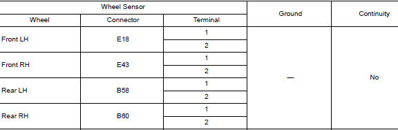
Is the inspection result normal? YES >> GO TO 5.
NO >> Repair the circuit.
5.CHECK WIRING HARNESS FOR OPEN CIRCUIT
Check continuity between ABS actuator and electric unit (control unit) connector E125 and wheel sensor connector of wheel with DTC.
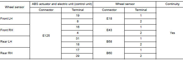
Is the inspection result normal? YES >> Replace the ABS actuator and electric unit (control unit). Refer to BRC-136, "Removal and Installation".
NO >> Repair the circuit.
 C1113, C1145, C1146 yaw rate/side/decel G sensor
DTC
Display Item
Malfunction detected condition
Possible causes
C1113
G SENSOR
When a malfunction is detected in longitudinal G sensor
signal.
Harness or ...
 C1120, C1122, C1124, C1126 ABS in valve system
DTC Logic
DTC DETECTION LOGIC
DTC
Display Item
Malfunction detected condition
Possible causes
C1120
FR LH IN ABS SOL
When a malfunction is detected in front LH ABS IN
...
Other materials:
Text messaging
WARNING
Laws in some jurisdictions may restrict
the use of “Text-to-Speech.” Check local
regulations before using the feature.
Laws in some jurisdictions may restrict
the use of some of the applications and
features, such as social networking and
te ...
Preparation
Special Service Tool
The actual shape of the tools may differ from those illustrated here.
Tool number
(TechMate No.)
Tool name
Description
—
(J-46534)
Trim Tool Set
Removing trim components
Commercial Service Tools
(TechMate No ...
EPS warning lamp
Component Function Check
1.CHECK THE ILLUMINATION OF THE EPS WARNING LAMP
Check that the EPS warning lamp turns ON when ignition switch turns ON. Then,
EPS warning lamp turns
OFF after the engine is started.
Is the inspection result normal?
YES >> Inspection End.
NO >> Perfor ...
