Nissan Rogue Service Manual: C1111 pump motor
DTC Logic
DTC DETECTION LOGIC
| DTC | Display Item | Malfunction detected condition | Possible causes |
| C1111 | PUMP MOTOR | When a malfunction is detected in motor or motor relay. |
|
DTC CONFIRMATION PROCEDURE
1.CHECK SELF-DIAGNOSTIC RESULT
 With CONSULT.
- Turn ignition switch OFF.
- Depress brake pedal 20 times or more.
- Start the engine and wait for 3 minutes or more.
- Perform self-diagnostic result.
Is DTC C1111 detected? YES >> Proceed to diagnosis procedure. Refer to BRC-82, "Diagnosis Procedure".
NO >> Inspection End.
Diagnosis Procedure
Regarding Wiring Diagram information, refer to BRC-57, "Wiring Diagram".
1.CONNECTOR INSPECTION
- Turn ignition switch OFF.
- Disconnect ABS actuator and electric unit (control unit) connectors.
- Check connectors and terminals for deformation, disconnection, looseness or damage.
Is the inspection result normal? YES >> GO TO 2.
NO >> Repair or replace as necessary.
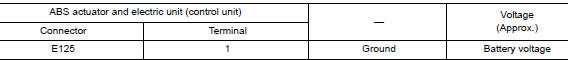
2.CHECK ABS MOTOR AND MOTOR RELAY BATTERY POWER SUPPLY
Check voltage between ABS actuator and electric unit (control unit) connector E125 terminal 1 and ground.
Is the inspection result normal? YES >> GO TO 3.
NO >> Repair or replace malfunctioning components.
3.CHECK ABS ACTUATOR AND ELECTRIC UNIT (CONTROL UNIT) GROUND CIRCUIT
Check continuity between ABS actuator and electric unit (control unit) connector E125 terminals 13, 38 and ground.

Is the inspection result normal? YES >> Replace ABS actuator and electric unit (control unit). Refer to BRC-136, "Removal and Installation" NO >> Repair or replace harness.
 C1109 power and ground system
DTC Logic
DTC DETECTION LOGIC
DTC
Display Item
Malfunction detected condition
Possible causes
C1109
BATTERY VOLTAGE
[ABNORMAL]
When ignition voltage is 10 ...
 C1113, C1145, C1146 yaw rate/side/decel G sensor
DTC
Display Item
Malfunction detected condition
Possible causes
C1113
G SENSOR
When a malfunction is detected in longitudinal G sensor
signal.
Harness or ...
Other materials:
U110f lost communication (ECM)
DTC Description
DTC DETECTION LOGIC
DTC
CONSULT screen terms
(Trouble diagnosis content)
DTC detection condition
U110F
LOST COMM (ECM)
(Lost Communication With ECM)
When the ignition switch is ON, TCM is unable to receive the CAN
communications
signal from ...
Unit removal and installation
TRANSAXLE ASSEMBLY
Exploded View
Transaxle assembly
O-ring
CVT fluid charging pipe
CVT fluid charging pipe cap
For the tightening torque, refer to TM-220, "Removal and
Installation".
Always replace after every
disassembly.
: N·m (kg-m, ft-lb)
: N·m ...
Power window relay
Description
Power is supplied to the main power window and door lock/unlock with BCM
control.
Component Function Check
1. CHECK POWER WINDOW RELAY POWER SUPPLY CIRCUIT
Check that an operation noise of power window relay [located behind the A/C
switch assembly (automatic A/
C) or Front air c ...
