Nissan Rogue Service Manual: C1109 power and ground system
DTC Logic
DTC DETECTION LOGIC
| DTC | Display Item | Malfunction detected condition | Possible causes |
| C1109 | BATTERY VOLTAGE [ABNORMAL] |
|
|
DTC CONFIRMATION PROCEDURE
1.CHECK SELF-DIAGNOSTIC RESULT
 With CONSULT.
- Turn the ignition switch OFF to ON.
- Perform self-diagnostic result.
Is DTC C1109 detected? YES >> Proceed to diagnosis procedure. Refer to BRC-80, "Diagnosis Procedure".
NO >> Inspection End.
Diagnosis Procedure
Regarding Wiring Diagram information, refer to BRC-57, "Wiring Diagram".
1.CONNECTOR INSPECTION
- Turn ignition switch OFF.
- Disconnect ABS actuator and electric unit (control unit) connectors.
- Check connectors and terminals for deformation, disconnection, looseness or damage.
Is the inspection result normal? YES >> GO TO 2.
NO >> Repair or replace as necessary.
2.CHECK ABS ACTUATOR AND ELECTRIC UNIT (CONTROL UNIT) IGNITION POWER SUPPLY CIRCUIT
Check voltage between ABS actuator and electric unit (control unit) connector E125 terminal 28 and ground.
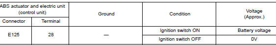
Is the inspection result normal? YES >> GO TO 3.
NO >> Repair or replace malfunctioning components.
3.CHECK ABS ACTUATOR AND ELECTRIC UNIT (CONTROL UNIT) BATTERY POWER SUPPLY CIRCUIT
Check voltage between ABS actuator and electric unit (control unit) connector E125 terminals 1, 25 and ground.

Is the inspection result normal? YES >> GO TO 4.
NO >> Repair or replace malfunctioning components.
4.CHECK ABS ACTUATOR AND ELECTRIC UNIT (CONTROL UNIT) GROUND CIRCUIT
- Turn ignition switch OFF.
- Check continuity between ABS actuator and electric unit (control unit) connector E125 terminals 13, 38 and ground.
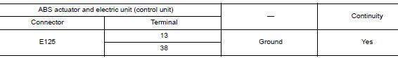
Is the inspection result normal? YES >> Replace ABS actuator and electric unit (control unit). Refer to BRC-136, "Removal and Installation".
NO >> Repair or replace malfunctioning components.
 C1105, C1106, C1107, C1108 wheel sensor
DTC Logic
DTC DETECTION LOGIC
DTC
Display Item
Malfunction detected condition
Possible causes
C1105
RR RH SENSOR-2
When distance between rear ...
 C1111 pump motor
DTC Logic
DTC DETECTION LOGIC
DTC
Display Item
Malfunction detected condition
Possible causes
C1111
PUMP MOTOR
When a malfunction is detected in motor or motor relay.
...
Other materials:
Unit disassembly and assembly
FRONT COMBINATION LAMP
Exploded View
Front combination lamp
Parking (side marker) lamp bulb socket
Headlamp (low beam) bulb
Plastic cover
Headlamp (high beam) bulb
Turn signal lamp bulb socket
Disassembly and Assembly
DISASSEMBLY
Remove front combinat ...
Basic inspection
DIAGNOSIS AND REPAIR WORK FLOW
Work Flow
OVERALL SEQUENCE
DETAILED FLOW
1.OBTAIN INFORMATION ABOUT SYMPTOM
Interview the customer to obtain as much information as possible about the
conditions and environment under
which the malfunction occurred.
>> GO TO 2.
2.CHECK SYMPTOM
...
Wiring diagram
NAVIGATION WITH BOSE
Wiring Diagram
...
