Nissan Rogue Service Manual: Moonroof switch
Description
Transmits switch operation signal to moonroof motor and sunshade motor assembly.
Diagnosis Procedure
Regarding Wiring Diagram information, refer to RF-17, "Wiring Diagram".
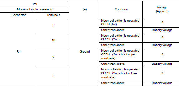
1.CHECK MOONROOF SWITCH INPUT SIGNAL
- Turn ignition switch ON.
- Check voltage between moonroof motor assembly harness connector and ground.
Is the inspection result normal? YES >> Inspection End.
NO >> GO TO 2.
2.CHECK MOONROOF SWITCH CIRCUIT
- Turn ignition switch OFF.
- Disconnect moonroof motor assembly connector and moonroof switch connector.
- Check continuity between moonroof motor assembly harness connector and moonroof switch harness connector.

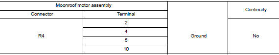
- Check continuity between moonroof motor assembly harness connector and ground.
Is the inspection result normal? YES >> GO TO 3.
NO >> Repair or replace the harness.
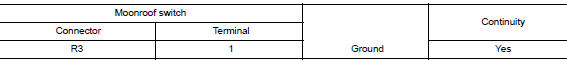
3.CHECK MOONROOF SWITCH GROUND CIRCUIT
Check continuity between moonroof switch harness connector and ground.
Is the inspection result normal? YES >> GO TO 4.
NO >> Repair or replace the harness.
4.CHECK MOONROOF SWITCH
Check moonroof switch.
Refer to RF-32, "Component Inspection".
Is the inspection result normal? YES >> GO TO 5.
NO >> Replace moonroof switch. Refer to RF-64, "Removal and Installation".
5.CHECK INTERMITTENT INCIDENT
Refer to GI-41, "Intermittent Incident".
>> Inspection End.
Component Inspection
MOONROOF SWITCH
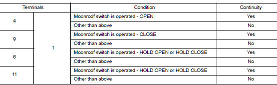
1. CHECK MOONROOF SWITCH
- Turn ignition switch OFF.
- Disconnect moonroof switch.
- Check continuity between moonroof switch terminals.
Is the inspection result normal? YES >> Moonroof switch is OK.
NO >> Replace moonroof switch. Refer to RF-64, "Removal and Installation".
 Power supply and ground circuit
BCM (BODY CONTROL SYSTEM) (WITH INTELLIGENT KEY SYSTEM)
BCM (BODY CONTROL SYSTEM) (WITH INTELLIGENT KEY SYSTEM) : Diagnosis
Procedure
Regarding Wiring Diagram information, refer to BCS-50, "Wi ...
 Door switch
WITH INTELLIGENT KEY
WITH INTELLIGENT KEY : Component Function Check
1.CHECK FUNCTION
Select "DOOR LOCK" of "BCM" using CONSULT.
Select "DOOR SW-DR", ...
Other materials:
Front wiper and washer system
Wiring Diagram
...
Crash zone sensor
Exploded View
Crash zone sensor
Crash zone sensor harness
connector
Bracket
Removal and Installation
WARNING:
Before servicing the SRS, turn ignition switch OFF, disconnect
both battery terminals then wait at
least three minutes.
Do not use a ...
CD care and cleaning
Handle a CD by its edges. Do not bend the
disc. Never touch the surface of the disc.
Always place the discs in the storage case
when they are not being used.
To clean a disc, wipe the surface from the
center to the outer edge using a clean, soft
cloth. Do not wipe the ...
