Nissan Rogue Service Manual: Power supply and ground circuit
BCM (BODY CONTROL SYSTEM) (WITH INTELLIGENT KEY SYSTEM)
BCM (BODY CONTROL SYSTEM) (WITH INTELLIGENT KEY SYSTEM) : Diagnosis Procedure
Regarding Wiring Diagram information, refer to BCS-50, "Wiring Diagram".
1. CHECK FUSE
Check that the following fuse is not blown.

Is the fuse blown? YES >> Replace the blown fuse after repairing the affected circuit.
NO >> GO TO 2.
2. CHECK POWER SUPPLY CIRCUIT
- Disconnect BCM connector M20.
- Check voltage between BCM connector M20 and ground.
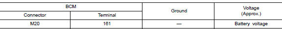
Is the inspection result normal? YES >> GO TO 3.
NO >> Repair or replace harness or connectors.
3. CHECK GROUND CIRCUIT
Check continuity between BCM connector M20 and ground.
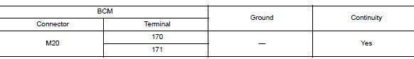
Is the inspection result normal? YES >> Inspection End.
NO >> Repair or replace harness or connectors.
BCM (BODY CONTROL SYSTEM) (WITHOUT INTELLIGENT KEY SYSTEM)
BCM (BODY CONTROL SYSTEM) (WITHOUT INTELLIGENT KEY SYSTEM) : Diagnosis Procedure
Regarding Wiring Diagram information, refer to BCS-110, "Wiring Diagram".
1. CHECK FUSE
Check that the following fuse is not blown.

Is the fuse blown? YES >> Replace the blown fuse after repairing the affected circuit.
NO >> GO TO 2.
2. CHECK POWER SUPPLY CIRCUIT
- Disconnect BCM connector M20.
- Check voltage between BCM connector M20 and ground.

Is the inspection result normal? YES >> GO TO 3.
NO >> Repair or replace harness or connectors.
3. CHECK GROUND CIRCUIT
Check continuity between BCM connector M20 and ground.
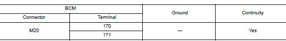
Is the inspection result normal? YES >> Inspection End.
NO >> Repair or replace harness or connectors.
MOONROOF MOTOR ASSEMBLY
MOONROOF MOTOR ASSEMBLY : Description
- BCM supplies the moonroof motor assembly with power.
- CPU is integrated in moonroof motor assembly.
- Tilts up/down & slides open/close by moonroof switch operation.
- In order to close the moonroof during high speed driving, the Combination meter will send a speed signal to the moonroof CPU to adjust the torque of the motor during the tilt-down operation.
MOONROOF MOTOR ASSEMBLY : Component Function Check
1. CHECK MOONROOF MOTOR FUNCTION
Does the tilt up/down & slide open/close functions operate normally with moonroof switch? Is the inspection result normal? YES >> Moonroof motor assembly is OK.
NO >> Refer to RF-26, "MOONROOF MOTOR ASSEMBLY : Diagnosis Procedure".
MOONROOF MOTOR ASSEMBLY : Diagnosis Procedure
Regarding Wiring Diagram information, refer to RF-17, "Wiring Diagram".
MOONROOF MOTOR ASSEMBLY
1. CHECK POWER SUPPLY CIRCUIT
- Turn ignition switch OFF.
- Disconnect the moonroof motor assembly connector.
- Turn ignition switch ON.
- Check voltage between moonroof motor assembly connector and ground.
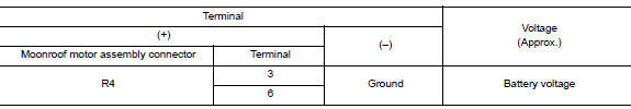
Is the inspection result normal? YES >> GO TO 2.
NO >> GO TO 3.
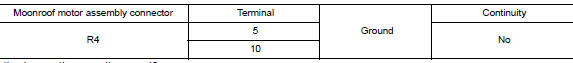
2. CHECK GROUND CIRCUIT
- Turn ignition switch OFF.
- Check continuity between moonroof motor assembly connector and ground.

Is the inspection result normal? YES >> GO TO 5.
NO >> Repair or replace harness.
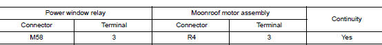
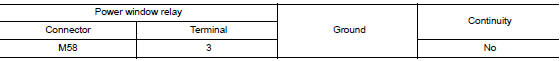
3.CHECK HARNESS CONTINUITY
- Turn ignition switch OFF.
- Disconnect power window relay connector.
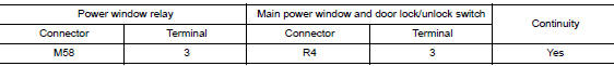
- Check continuity between power window relay harness connector and moonroof motor assembly harness connector.
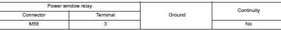
- Check continuity between power window relay harness connector and ground.
Is the inspection result normal? YES >> Refer to PWC-48, "Diagnosis Procedure".
NO >> Repair or replace harness.
4. CHECK MOONROOF SWITCH INPUT SIGNAL
- Connect moonroof motor assembly.
- Turn ignition switch ON.
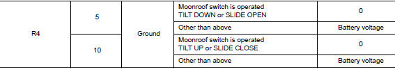
- Check voltage between the moonroof motor assembly connector and ground.

Is the inspection result normal? YES >> GO TO 8.
NO >> GO TO 6.
5. CHECK MOONROOF SWITCH CIRCUIT
- Turn ignition switch OFF.
- Disconnect the moonroof motor assembly and moonroof switch.
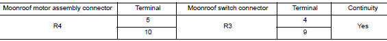
- Check continuity between the moonroof motor assembly connector and moonroof switch connector.
- Check continuity between the moonroof motor assembly connector and ground.
Is the inspection result normal? YES >> GO TO 7.
NO >> Repair or replace harness.
6. CHECK MOONROOF SWITCH GROUND CIRCUIT
- Connect moonroof motor assembly.
- Check continuity between the moonroof switch connector and ground.

Is the inspection result normal? YES >> Refer to RF-32, "Component Inspection".
NO >> Repair or replace harness.
7. CHECK COMBINATION METER SIGNAL
- Connect the moonroof motor assembly connector.
- Turn ignition switch ON.
- Check the signal between the moonroof motor assembly connector and ground with oscilloscope.
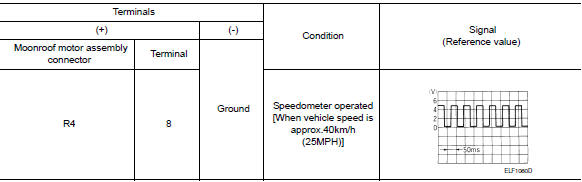
Is the inspection result normal? YES >> Replace moonroof motor assembly. Refer to RF-53, "Removal and Installation". After that, refer to RF-24, "ADDITIONAL SERVICE WHEN REPLACING CONTROL UNIT : Special Repair Requirement".
NO >> GO TO 9.
8.CHECK COMBINATION METER CIRCUIT
- Turn ignition switch OFF.
- Disconnect combination meter.
- Check continuity between the combination meter connector and the moonroof motor assembly connector.

- Check continuity between the combination meter connector and ground.

Is the inspection result normal? YES >> Replace combination meter. Refer to BCS-76, "Removal and Installation".
NO >> Repair or replace harness.
MOONROOF MOTOR ASSEMBLY : Special Repair Requirement
1. PERFORM INITIALIZATION PROCEDURE
Perform the initialization procedure.
Refer to RF-29, "MOONROOF MOTOR ASSEMBLY : Special Repair Requirement".
>> GO TO 2.
2. CHECK ANTI-PINCH OPERATION
Check the anti-pinch operation.
Refer to RF-29, "MOONROOF MOTOR ASSEMBLY : Special Repair Requirement".
Is the inspection result normal? YES >> Inspection End.
NO >> Check fitting adjustment.
SUNSHADE MOTOR ASSEMBLY
SUNSHADE MOTOR ASSEMBLY : Description
- BCM supplies the sunshade motor assembly with power.
- CPU is integrated in sunshade motor assembly.
- Slide open/close controlled by the moonroof switch operation.
SUNSHADE MOTOR ASSEMBLY : Component Function Check
1. CHECK SUNSHADE MOTOR FUNCTION
Does the slide open and close functions operate normally with the moonroof switch? Is the inspection result normal? YES >> Sunshade motor assembly is OK.
NO >> Refer to RF-29, "SUNSHADE MOTOR ASSEMBLY : Diagnosis Procedure".
SUNSHADE MOTOR ASSEMBLY : Diagnosis Procedure
1.CHECK POWER SUPPLY
- Turn ignition switch OFF.
- Disconnect sunshade motor assembly connector.
- Turn ignition switch ON.
- Check voltage between sunshade motor assembly harness connector and ground.
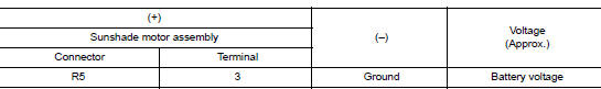
Is the inspection result normal? YES >> GO TO 2.
NO >> GO TO 3.
2.CHECK GROUND CIRCUIT
- Turn ignition switch OFF.
- Check continuity between sunshade motor assembly harness connector and ground.

Is the inspection result normal? YES >> GO TO 4.
NO >> Repair or replace the harness.
3.CHECK HARNESS CONTINUITY
- Turn ignition switch OFF.
- Disconnect power window relay connector.
- Check continuity between power window relay harness connector and moonroof motor assembly harness connector.
- Check continuity between power window relay harness connector and ground.
Is the inspection result normal? YES >> Refer to PWC-48, "Diagnosis Procedure".
NO >> Repair or replace harness.

 Moonroof switch
Description
Transmits switch operation signal to moonroof motor and sunshade motor
assembly.
Diagnosis Procedure
Regarding Wiring Diagram information, refer to RF-17, "Wiring Diagram".
...
Other materials:
Periodic maintenance
HEADLAMP AIMING ADJUSTMENT
Inspection
PREPARATION BEFORE ADJUSTING
Before performing aiming adjustment, check the following:
Make sure all tires are inflated to correct pressure.
Place vehicle and screen on level surface.
Make sure there is no load in vehicle other than ...
B142X collision detection
Description
DTC B1209 - B1211 COLLISION DETECTION
The air bag diagnosis sensor unit will set this DTC if it has detected a
collision which has resulted in a deployment
of one or more air bags or pre-tensioners. If this DTC is detected after a SRS
repair, the air bag diagnosis
sensor unit has ...
B0096 front side air bag satellite sensor RH
Description
DTC B0096 FRONT SATELLITE SENSOR RH
The front side air bag satellite sensor RH is wired to the air bag diagnosis
sensor unit. The air bag diagnosis
sensor unit will monitor the front side air bag satellite sensor RH for internal
failures and its circuits for communication
errors. ...
