Nissan Rogue Service Manual: Preparation
Special service tools
The actual shape of the tools may differ from those illustrated here.
|
Tool number (TechMate No.) Tool name |
Description | |
| — (J-48891) Spark plug socket | 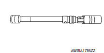 |
Removing and installing spark plug |
| KV10111100 (J-37228) Seal cutter |  |
Removing oil pan and timing chain case |
| KV10112100 (BT-8653-A) Torque angle meter |  |
Tightening bolts for bearing cap, cylinder head, etc. |
Commercial service tools
|
Tool number (TechMate No.) Tool name |
Description |
|
| Pulley puller |
|
Removing crankshaft pulley |
| Piston ring compresso |
|
Installing piston assembly into cylinder bore |
| Pulley holder |
|
Crankshaft pulley removing and installing |
| Valve seat cutter set |
|
Finishing valve seat dimensions |
| Socket |
|
Removing and installing flywheel Size: T55 |
| Piston ring expander |
|
Removing and installing piston ring |
| Valve guide drift |
|
Removing and installing valve guide
Intake & Exhaust: a: 9.5 mm (0.374 in) dia. b: 5.5 mm (0.217 in) dia. |
| Valve guide reamer |
|
Intake & Exhaust: |
| Anti-seize lubricant i.e.: (PermatexTM 133AR or equivalent meeting MIL specification MIL-A-907) |
|
Lubricating oxygen sensor thread cleaning tool when reconditioning exhaust system threads |
| Manual lift table caddy |
|
Removing and installing engine |
| KV10107902 (J-38959) Valve oil seal puller with adapter (1) |
|
Removing valve oil seal |
| KV10115600 (J-38958) Valve oil seal drift |
|
Installing valve oil seal Use side A. Unit: mm (in) |
| Tube presser |
|
Pressing the tube of liquid gasket |
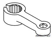
| Exhaust gas sensor wrench |
|
Removing exhaust gas sensor |
| KV10116200 (J-26336-A) Valve spring compressor 1. KV10115900 (J-26336-20) Attachment 2. KV10109220 ( — ) Adapter |
|
Disassembling valve mechanism Part (1) is a component of KV10116200 (J- 26336-A), but part (2) is not. |


 Symptom diagnosi
NOISE, VIBRATION, AND HARSHNESS (NVH) TROUBLESHOOTING
NVH troubleshooting - engine noise
Valve mechanism
Intake and exhaust valve
Water pump
Timing chain
Dr ...

Other materials:
Precaution
Precaution for Supplemental Restraint System (SRS) "AIR BAG" and "SEAT
BELT
PRE-TENSIONER"
The Supplemental Restraint System such as “AIR BAG” and “SEAT BELT
PRE-TENSIONER”, used along
with a front seat belt, helps to reduce the risk or severity of injury to the
...
P0890 TCM
DTC Description
DTC DETECTION LOGIC
DTC
CONSULT screen terms
(Trouble diagnosis content)
DTC detection condition
P0890
TCM
(Transmission Control Module Power Relay
Sense Circuit Low)
When all of the following conditions are satisfied and this state is
maint ...
P0181 FTT sensor
DTC Description
DTC DETECTION LOGIC
DTC No.
CONSULT screen terms
(Trouble diagnosis content)
DTC detecting condition
P0181
FTT SENSOR
(Fuel temperature sensor ″A″ circuit range/
performance)
A
Rationally incorrect voltage from the sensor is sent ...
