Nissan Rogue Service Manual: Brake pedal position switch
Component Function Check
1.CHECK BRAKE PEDAL POSITION SWITCH FUNCTION
 With CONSULT
- Turn ignition switch ON.
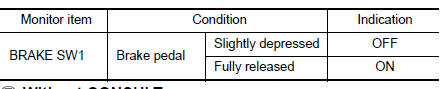
- Select “BRAKE SW1” in “DATA MONITOR” mode with CONSULT.
- Check “BRAKE SW1” indication as per the following conditions.
 Without CONSULT
- Turn ignition switch ON.
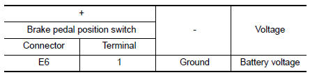
- Check the voltage between ECM harness connector terminals.

Is the inspection result normal? YES >> INSPECTION END
NO >> Proceed to EC-455, "Diagnosis Procedure".
Diagnosis Procedure
1.CHECK BRAKE PEDAL POSITION SWITCH POWER SUPPLY CIRCUIT
- Turn ignition switch OFF.
- Disconnect brake pedal position switch harness connector.
- Turn ignition switch ON.
- Check the voltage between brake pedal position switch harness connector and ground.
Is the inspection result normal? YES >> GO TO 3.
NO >> GO TO 2.
2.CHECK BRAKE PEDAL POSITION SWITCH POWER SUPPLY CIRCUIT
- Turn ignition switch OFF.
- Disconnect fuse block (J/B) harness connector.
- Check the continuity between brake pedal position switch harness connector and fuse block (J/B) harness connector.
Is the inspection result normal? YES >> Perform the trouble diagnosis for power supply circuit.
NO >> Repair or replace error-detected parts.
3.CHECK BRAKE PEDAL POSITION SWITCH INPUT SIGNAL CIRCUIT
- Turn ignition switch OFF.
- Disconnect ECM harness connector.
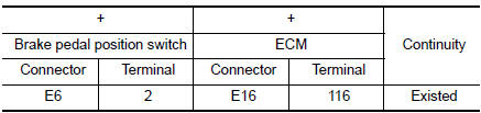
- Check the continuity between brake pedal position switch harness connector and ECM harness connector.
- Also check harness for short to ground and to power.
Is the inspection result normal? YES >> GO TO 4.
NO >> Repair open circuit, short to ground or short to power in harness or connectors.
4.CHECK BRAKE PEDAL POSITION SWITCH
Check brake pedal position switch. Refer to EC-456, "Component Inspection (Brake Pedal Position Switch)".
Is the inspection result normal? YES >> Check intermittent incident. Refer to GI-41, "Intermittent Incident".
NO >> Replace brake pedal position switch. Refer to BR-20, "Exploded View".
Component Inspection (Brake Pedal Position Switch)
1.CHECK BRAKE PEDAL POSITION SWITCH-1
- Turn ignition switch OFF.
- Disconnect brake pedal position harness connector.
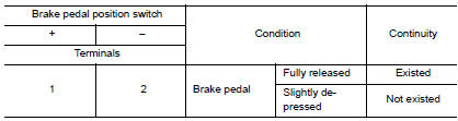
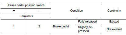
- Check the continuity between brake pedal position switch terminals as per the following conditions.
Is the inspection result normal? YES >> INSPECTION END
NO >> GO TO 2.
2.CHECK BRAKE PEDAL POSITION SWITCH-2
- Adjust brake pedal position switch installation. Refer to BR-15, "Adjustment".
- Check the continuity between brake pedal position switch terminals as per the following conditions.
Is the inspection result normal?
YES >> INSPECTION END
NO >> Replace brake pedal position switch. Refer to BR-20, "Exploded View".
 P2610 ECM internal timer
Description
This ECM contains a timer and measures time between an ignition switch OFF
and the next ignition switch
ON. This enables the judging of the state of engine cooling at an engine start.
...
 Cooling fan
Component Function Check
1.CHECK COOLING FAN FUNCTION
With CONSULT
Turn ignition switch ON.
Perform “COOLING FAN (DUAL)” in “ACTIVE TEST” mode of “IPDM E/R”
using CO ...
Other materials:
Rocker cover
Oil filler cap
Rocker cover
Rocker cover gasket
Refer to INSTALLATION
Engine front
Removal and Installation
REMOVAL
Remove intake manifold. Refer to EM-26, "Removal and
Installation".
Remove wheel and tire (RH) using a power to ...
Unit disassembly and assembly
CENTER CONSOLE ASSEMBLY
Exploded View
Center console cup holder (without
heated seats)
Coin tray insert
Center console cup holder (with
heated seats)
Front heated seat switch (RH)
Front heated seat switch (LH)
Shift selector finisher
Shift selector ...
B2268 water temp
Description
The engine coolant temperature signal is transmitted from ECM to the
combination meter via CAN communication.
DTC Logic
DTC DETECTION LOGIC
DTC
CONSULT
Detection Condition
Possible Cause
B2268
WATER TEMP
[B2268]
ECM continuously tra ...
