Nissan Rogue Service Manual: Brake pedal
Exploded View
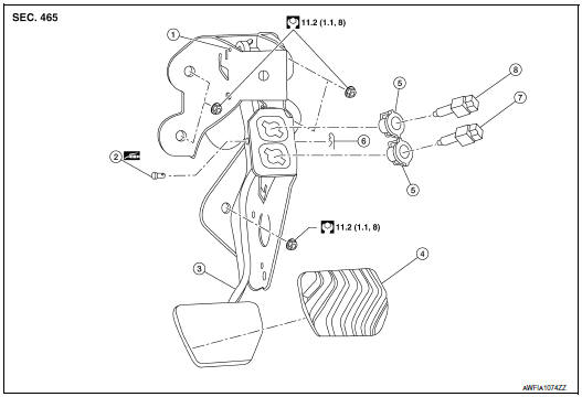
- Rivet
- Clevis pin
- Brake pedal
- Brake pedal pad
- Clip
- Snap pin
- Stop lamp switch
- Brake pedal position switch
Removal and Installation
REMOVAL
- Remove instrument lower panel LH. Refer to IP-22, "Removal and Installation".
- Remove the knee protector. Refer to IP-14, "Exploded View".
- Remove snap pin and clevis pin from clevis of brake booster.
- Disconnect the harness connectors from the stop lamp switch and brake pedal position switch.
- Remove the accelerator pedal. Refer to ACC-3, "Removal and Installation".
- Remove the brake pedal.
CAUTION: Support the brake booster and master cylinder to prevent contact with other components.
INSPECTION AFTER REMOVAL
- Check the following items and replace the brake pedal assembly if necessary.
- Check the brake pedal rivet for deformation or damage.
- Check the brake pedal for bend, damage, and cracks on the welded parts.
- Check clevis pin and plastic stopper (A) for damage and deformation.
If any damage is found, replace clevis pin.
INSTALLATION
Installation is in the reverse order of removal.
CAUTION: Replace the brake pedal if it has been dropped or sustained an impact.
- Check that the brake pedal height and brake pedal play meet the specifications by checking the brake pedal and brake booster for damage and replace parts as necessary. Refer to BR-54, "Brake Pedal".

 Brake piping
FRONT
FRONT : Exploded View
Master cylinder secondary to
ABS actuator brake tube
Master cylinder primary to
ABS actuator brake tube
Brake tube bracket
Brake tube (LH)
Brake ...
Other materials:
The seat belt reminder warning continues sounding, or
does not sound
Description
Seat belt warning does not sound even though driver seat belt is not
fastened.
Seat belt warning sounds even though driver seat belt is fastened.
Diagnosis Procedure
1.CHECK WARNING CHIME OPERATION
Select "BUZZER" of "BCM" on "CONSULT" ...
Front wiper auto stop signal circuit
Component Function Check
1. CHECK FRONT WIPER (AUTO STOP) SIGNAL
Select FR WIPER STOP of BCM (WIPER) data monitor item.
Operate the front wiper.
Check that FR WIPER STOP changes from ON to OFF according to the
wiper position
Is the inspection result normal?
YES ...
Intermittent incident
DESCRIPTION
Sometimes the symptom is not present when the vehicle is brought in for
service. If possible, re-create the
conditions present at the time of the incident. Doing so may help avoid a No
Trouble Found Diagnosis. The following section illustrates ways to simulate the
conditions/envi ...
