Nissan Rogue Service Manual: Basic inspection
Work Procedure
1.INSPECTION START
- Check service records for any recent repairs that may indicate a related malfunction, or a current need for scheduled maintenance.
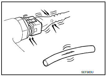
- Open engine hood and check the following:
- Harness connectors for improper connections
- Wiring harness for improper connections, pinches and cut
- Vacuum hoses for splits, kinks and improper connections
- Hoses and ducts for leaks
- Air cleaner clogging
- Gasket
- Confirm that electrical or mechanical loads are not applied.
- Headlamp switch is OFF.
- Air conditioner switch is OFF.
- Rear window defogger switch is OFF.
- Steering wheel is in the straight-ahead position, etc.
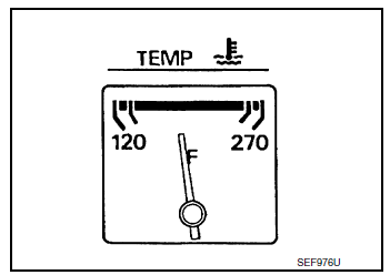
- Start engine and warm it up until engine coolant temperature
indicator points the middle of gauge.
Ensure engine stays below 1,000 rpm.
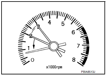
- Run engine at about 2,000 rpm for about 2 minutes under no load.
- Make sure that no DTC is displayed with CONSULT or GST.
Is any DTC detected? YES >> GO TO 2.
NO >> GO TO 3.

2.REPAIR OR REPLACE
Repair or replace components as necessary according to corresponding Diagnostic Procedure.
>> GO TO 3.
3.CHECK TARGET IDLE SPEED
- Run engine at about 2,000 rpm for about 2 minutes under no load.
- Rev engine (2,000 to 3,000 rpm) two or three times under no load, then run engine at idle speed for about 1 minute.
- Check idle speed.
For procedure, refer to EC-493, "Inspection".
For specification, refer to EC-500, "Idle Speed".
Is the inspection result normal? YES >> GO TO 10.
NO >> GO TO 4.
4.PERFORM ACCELERATOR PEDAL RELEASED POSITION LEARNING
- Stop engine.
- Perform EC-139, "Work Procedure".
>> GO TO 5.
5.PERFORM THROTTLE VALVE CLOSED POSITION LEARNING
Perform EC-140, "Work Procedure".
>> GO TO 6.
6.PERFORM IDLE AIR VOLUME LEARNING
Perform EC-141, "Work Procedure".
Is Idle Air Volume Learning carried out successfully? YES >> GO TO 7.
NO >> Follow the instruction of Idle Air Volume Learning. Then GO TO 4.
7.CHECK TARGET IDLE SPEED AGAIN
- Start engine and warm it up to normal operating temperature.
- Check idle speed.
For procedure, refer to EC-493, "Inspection".
For specification, refer to EC-500, "Idle Speed".
Is the inspection result normal? YES >> GO TO 10.
NO >> GO TO 8.
8.DETECT MALFUNCTIONING PART
Check the Following.
- Check camshaft position sensor (PHASE) and circuit. Refer to EC-298, "DTC Description".
- Check crankshaft position sensor (POS) and circuit. Refer to EC-295, "DTC Description".
Is the inspection result normal? YES >> GO TO 9.
NO >> Repair or replace. Then GO TO 4
9.CHECK ECM FUNCTION
- Substitute another known-good ECM to check ECM function. (ECM may be the cause of an incident, but this is a rare case.)
- Perform initialization of NVIS (NATS) system and registration of all NVIS (NATS) ignition key IDs. Refer to SEC-65, "ECM : Work Procedure" (With intelligent key system) or SEC-153, "ECM RE-COMMUNICATING FUNCTION : Special Repair Requirement" (Without intelligent key system).
>> GO TO 4.
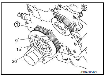
10.CHECK IGNITION TIMING
- Run engine at idle.
- Check ignition timing with a timing light.
For procedure, refer to EC-494, "Inspection" For specification, refer to EC-500, "Ignition Timing".
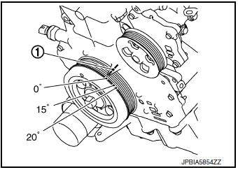
1 Timing indicator
Is the inspection result normal? YES >> INSPECTION END.
NO >> GO TO 11.
11.PERFORM ACCELERATOR PEDAL RELEASED POSITION LEARNING
- Stop engine.
- Perform EC-139, "Work Procedure".
>> GO TO 12.
12.PERFORM THROTTLE VALVE CLOSED POSITION LEARNING
Perform EC-140, "Work Procedure".
>> GO TO 13.
13.PERFORM IDLE AIR VOLUME LEARNING
Perform EC-141, "Work Procedure".
Is Idle Air Volume Learning carried out successfully? YES >> GO TO 14.
NO >> Follow the instruction of Idle Air Volume Learning. Then GO TO 4.
14.CHECK TARGET IDLE SPEED AGAIN
- Start engine and warm it up to normal operating temperature.
- Check idle speed.
For procedure, refer to EC-493, "Inspection".
For specification, refer to EC-500, "Idle Speed".
Is the inspection result normal? YES >> GO TO 15.
NO >> GO TO 17.
15.CHECK IGNITION TIMING AGAIN
- Run engine at idle.
- Check ignition timing with a timing light.
For procedure, refer to EC-494, "Inspection".
For specification, refer to EC-500, "Ignition Timing".
1 Timing indicator
Is the inspection result normal? YES >> INSPECTION END.
NO >> GO TO 16.
16.CHECK TIMING CHAIN INSTALLATION
Check timing chain installation. Refer to EM-45, "Removal and Installation".
Is the inspection result normal? YES >> GO TO 17.
NO >> Repair the timing chain installation. Then GO TO 4.
17.DETECT MALFUNCTIONING PART
Check the following.
- Check camshaft position sensor (PHASE) and circuit. Refer to EC-298, "DTC Description".
- Check crankshaft position sensor (POS) and circuit. Refer to EC-295, "DTC Description".
Is the inspection result normal? YES >> GO TO 18.
NO >> Repair or replace. Then GO TO 4
18.CHECK ECM FUNCTION
- Substitute another known-good ECM to check ECM function. (ECM may be the cause of an incident, but this is a rare case.)
- Perform initialization of NVIS (NATS) system and registration of all NVIS (NATS) ignition key IDs. Refer to SEC-65, "ECM : Work Procedure" (With intelligent key system) or SEC-153, "ECM RE-COMMUNICATING FUNCTION : Special Repair Requirement" (Without intelligent key system).
>> GO TO 4.
 Diagnosis and repair workflow
Work Flow
OVERALL SEQUENCE
DETAILED FLOW
1.GET INFORMATION FOR SYMPTOM
Get the detailed information from the customer about the symptom (the
condition and the environment
when the inci ...
 Additional service when replacing ECM
Description
When replacing ECM, the following procedure must be performed. (For details,
refer to EC-136, "Work Procedure".)
PROGRAMMING OPERATION
NOTE:
After replacing with a blank EC ...
Other materials:
Removal and installation
REAR WHEEL HUB AND HOUSING
Exploded View
Axle housing
Suspension arm
Back plate
Hub bolt
Wheel hub and bearing
Wheel hub lock nut
Cotter pin
Disc brake rotor
Plug
Removal and Installation
REMOVAL
Remove the wheel and tire using power tool. Refer to ...
Precaution
Precaution for Supplemental Restraint System
(SRS) "AIR BAG" and "SEAT BELT PRE-TENSIONER"
The Supplemental Restraint System such as “AIR BAG” and “SEAT BELT PRE-TENSIONER”,
used along
with a front seat belt, helps to reduce the risk or severity of injury to the
dr ...
Parking/parking on hills
Parking/parking on hills
WARNING
Do not stop or park the vehicle over
flammable materials such as dry grass,
waste paper or rags. They may ignite
and cause a fire.
Safe parking procedures require that
both the parking brake be set and the
transmiss ...
