Nissan Rogue Service Manual: Basic inspection
DIAGNOSIS AND REPAIR WORK FLOW
Work Flow
OVERALL SEQUENCE
DETAILED FLOW
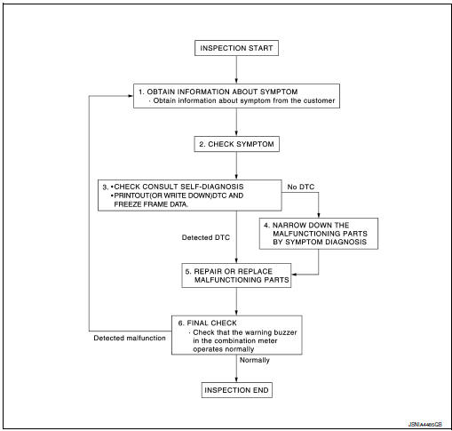
1.OBTAIN INFORMATION ABOUT SYMPTOM
Interview the customer to obtain as much information as possible about the conditions and environment under which the malfunction occurred.
>> GO TO 2.
2.CHECK SYMPTOM
- Check the symptom based on the information obtained from the customer.
- Check if any other malfunctions are present.
> GO TO 3.
3.CHECK CONSULT SELF-DIAGNOSIS RESULTS
- Connect CONSULT and perform "self-diagnosis". Refer to WCS-27, "DTC Index".
- When DTC is detected, follow the instructions below:
- Record DTC and Freeze Frame Data.
Are self-diagnosis results normal? YES >> GO TO 4.
NO >> GO TO 5.
4.NARROW DOWN MALFUNCTIONING PARTS BY SYMPTOM DIAGNOSIS
Perform symptom diagnosis and narrow down the malfunctioning parts.
>> GO TO 5.
5.REPAIR OR REPLACE MALFUNCTIONING PARTS
Repair or replace malfunctioning parts.
NOTE: If DTC is displayed, erase DTC after repairing or replacing malfunctioning parts.
>> GO TO 6.
6.FINAL CHECK
Check that the warning buzzer in the combination meter operates normally.
Does it operate normally? YES >> Inspection End.
NO >> GO TO 1.
 Wiring diagram
Wiring Diagram
...

Other materials:
All-wheel drive (AWD) lock switch (if so equipped)
All-wheel drive (AWD) lock switch (if so equipped)
The all-wheel drive (AWD) lock switch is locaton the instrument panel. The
AWD LOCK indicator
light will illuminate when the switch is turned
on. For additional information, refer to
“Warning/Indicator lights and audible reminders”
in ...
AM radio reception
AM signals, because of their low frequency, can
bend around objects and skip along the ground.
In addition, the signals can be bounced off the
ionosphere and bent back to earth. Because of
these characteristics, AM signals are also subject
to interference as they travel from transmitter
to r ...
Wiring diagram
EPS SYSTEM
Wiring Diagram
...
