Nissan Rogue Service Manual: Ambient sensor signal circuit
Description
It detects outside air temperature and converts it into a resistance value which is then input into the combination meter.
Diagnosis Procedure
Regarding Wiring Diagram information, refer to MWI-32, "Wiring Diagram".
1.CHECK AMBIENT SENSOR SIGNAL CIRCUIT
- Turn ignition switch OFF.
- Disconnect combination meter connector and ambient sensor connector.
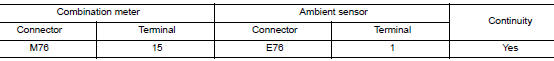
- Check continuity between combination meter harness connector and ambient sensor harness connector.
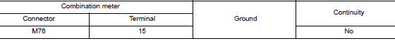
- Check continuity between combination meter harness connector and ground.
Is the inspection result normal? YES >> GO TO 2.
NO >> Repair or replace harness or connector.
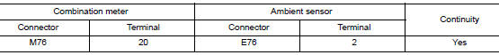
2.CHECK AMBIENT SENSOR SIGNAL GROUND CIRCUIT
Check continuity between combination meter harness connector and ambient sensor harness connector.
Is the inspection result normal? YES >> Inspection End.
NO >> Repair or replace harness or connector.
Component Inspection
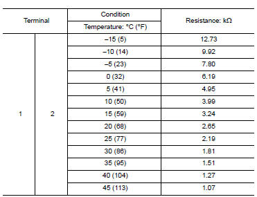
1.CHECK AMBIENT SENSOR
- Turn ignition switch OFF.
- Disconnect ambient sensor connector.
- Check resistance between ambient sensor terminals.
Is the inspection result normal? YES >> Inspection End.
NO >> Replace ambient sensor. Refer to HAC-104, "Removal and Installation".
 Parking brake switch signal circuit
Description
Transmits the parking brake switch signal to the combination meter.
Component Function Check
1.COMBINATION METER INPUT SIGNAL
Start engine.
Check "PKB SW" in ...
 Meter control switch signal circuit
Diagnosis Procedure
Regarding Wiring Diagram information, refer to MWI-32, "Wiring Diagram".
1.CHECK METER CONTROL SWITCH SIGNAL
Turn ignition switch ON.
Check voltage be ...
Other materials:
Console box
Console box
Upper half
Pull up on the driver’s side latch to open the
upper half of the console box.
The upper half of the console box may be used for
storage of cellular phones. An access hole is
provided at the front of the upper half of the
console box for a phone or iPod® cord rout ...
Periodic maintenance
FUEL SYSTEM
Inspection
Inspect fuel lines, fuel filler cap, and fuel tank for improper attachment,
leaks, cracks, damage, loose connections, chafing or deterioration.
(A) : Engine
(B) : Fuel line
(C) : Fuel tank
If necessary, repair or replace damaged parts.
Quick Connector
CAUTION:
...
Front wiper drive assembly
Exploded View
REMOVAL
Cowl top
Front wiper drive assembly
Removal and Installation
REMOVAL
Remove cowl top cover. Refer to EXT-25, "Removal and
Installation".
Disconnect harness connector from front wiper motor.
Remove bolts and front wiper driv ...
