Nissan Rogue Service Manual: Meter control switch signal circuit
Diagnosis Procedure
Regarding Wiring Diagram information, refer to MWI-32, "Wiring Diagram".
1.CHECK METER CONTROL SWITCH SIGNAL
- Turn ignition switch ON.
- Check voltage between the following terminals of the meter control switch harness connector M3.
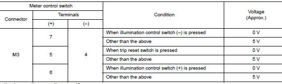
Is the inspection result normal? YES >> Inspection End.
NO >> GO TO 2.
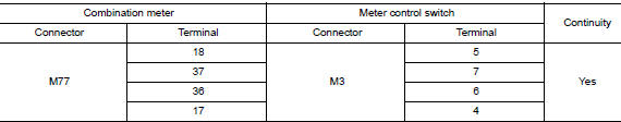
2.CHECK METER CONTROL SWITCH HARNESS
- Turn ignition switch OFF.
- Disconnect combination meter harness connector M77 and meter control switch harness connector M3.
- Check continuity between combination meter harness connector M77 and meter control switch harness connector M3.
- Check continuity between combination meter harness connector and ground.
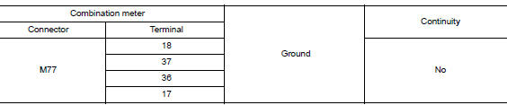
Is the inspection result normal? YES >> Inspection End.
NO >> Repair or replace harness or connectors.
Component Inspection
1.CHECK METER CONTROL SWITCH
- Turn ignition switch OFF.
- Disconnect meter control switch connector.
- Check meter control switch.
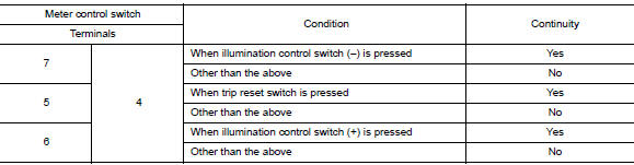
Is the inspection result normal? YES >> Inspection End.
NO >> Replace meter control switch. Refer to MWI-83, "Removal and Installation".
 Ambient sensor signal circuit
Description
It detects outside air temperature and converts it into a resistance value
which is then input into the combination
meter.
Diagnosis Procedure
Regarding Wiring Diagram information, r ...
 Steering switch
Description
When one of the steering switches is pushed, the resistance in the steering
switch changes the signal to
identify which button is controlling the information display.
Diagnosis Proced ...
Other materials:
Power switch illumination circuit
Description
Provides the power supply and the ground to control the power switch
illumination.
Component Function Check
1.CHECK POWER SWITCH ILLUMINATION OPERATION
CONSULT ACTIVE TEST
Turn the power switch ON.
Select “ENGINE SW ILLUMI” of “BCM” active test item.
&n ...
Compression pressure
CHECKING COMPRESSION PRESSURE
Warm up the engine to full operating temperature.
Release the fuel pressure. Refer to EC-144, "Work Procedure".
Remove the ignition coil and spark plug from each cylinder. Refer
to EM-36, "Removal and Installation"
and ...
Windshield wiper and washer switch
WARNINGIn freezing temperatures the washer solution
may freeze on the window and obscure
your vision which may lead to an
accident. Warm the window with the defroster
before you wash the window.
CAUTION
Do not operate the washer continuously
for ...
