Nissan Rogue Service Manual: Power switch illumination circuit
Description
Provides the power supply and the ground to control the power switch illumination.
Component Function Check
1.CHECK POWER SWITCH ILLUMINATION OPERATION
 CONSULT ACTIVE TEST
- Turn the power switch ON.
- Select “ENGINE SW ILLUMI” of “BCM” active test item.
- With operating the test items, check that the power switch illumination turns ON/OFF.
On : Power switch illumination ON
Off : Power switch illumination OFF
Does the power switch illumination turn ON/OFF? YES >> Power switch illumination circuit is normal.
NO >> Refer to INL-52, "Diagnosis Procedure".
Diagnosis Procedure
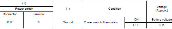
1.CHECK POWER SWITCH ILLUMINATION POWER SUPPLY OUTPUT
- Turn power switch OFF.
- Disconnect power switch connector.
- Check voltage between power switch harness connector and ground.
Is the inspection result normal? YES >> GO TO 4.
NO >> GO TO 2.
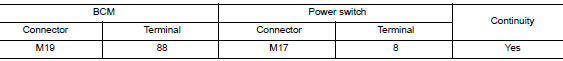
2.CHECK POWER SWITCH ILLUMINATION POWER SUPPLY OPEN CIRCUIT
- Turn the power switch OFF.
- Disconnect BCM connector.
- Check continuity between BCM harness connector and the power switch harness connector.
Is the inspection result normal? YES >> GO TO 3.
NO >> Repair or replace harnesses.
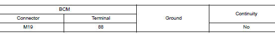
3.CHECK POWER SWITCH ILLUMINATION POWER SUPPLY SHORT CIRCUIT
Check continuity between BCM harness connector and ground.
Is the inspection result normal? YES >> Replace BCM. Refer to BCS-75, "Removal and Installation" (with intelligent Key system) or BCS- 135, "Removal and Installation" (without Intelligent Key system).
NO >> Repair or replace harnesses.
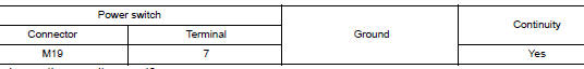
4.CHECK POWER SWITCH ILLUMINATION GROUND CIRCUIT
- Turn the power switch OFF.
- Check continuity between power switch harness connector and ground.
Is the inspection result normal? YES >> Replace power switch. Refer to SEC-112, "Removal and Installation".
NO >> Repair or replace harnesses.
 Luggage room lamp circuit
Description
Controls the luggage room lamp (ground side) to turn the luggage room lamp ON
and OFF.
Diagnosis Procedure
CAUTION:
Before performing the diagnosis, check that the following is norma ...
 Symptom diagnosis
INTERIOR LIGHTING SYSTEM SYMPTOMS
Symptom Table
CAUTION:
Perform the self-diagnosis with CONSULT before the symptom diagnosis. Perform
the trouble diagnosis
if any DTC is detected.
S ...
Other materials:
System description
DESCRIPTION
Engine Cooling System
Thermostat
Water outlet
Cylinder block (Thermostat housing)
Water inlet
Radiator
Water pump
Cylinder block
Cylinder head
Open
Closed
To electric throttle control actuator
To oil cooler
...
System
SRS AIR BAG SYSTEM
SRS AIR BAG SYSTEM : System Description
SYSTEM DIAGRAM
DESCRIPTION
The air bag deploys if the air bag diagnosis sensor unit is
activated while the ignition switch is in the ON or
START position.
The collision modes for which supplemental restraint sys ...
C1704, C1705, C1706, C1707 low tire pressure
DTC Logic
NOTE:
The Signal Tech II Tool [- (J-50190)] can be used to perform the following
functions. Refer to the Signal Tech II
User Guide for additional information.
Activate and display TPMS sensor IDs
Display tire pressure reported by the TPMS sensor
Read TPMS DTC ...
