
Nissan Rogue Service Manual: Diagnosis system (BCM) (without intelligent key system)
COMMON ITEM
COMMON ITEM : CONSULT Function (BCM - COMMON ITEM)
APPLICATION ITEM
CONSULT performs the following functions via CAN communication with BCM.
|
Direct Diagnostic Mode |
Description |
| Ecu Identification | The BCM part number is displayed. |
| Self Diagnostic Result | The BCM self diagnostic results are displayed. |
| Data Monitor | The BCM self diagnostic results are displayed. |
| Active Test | The BCM activates outputs to test components. |
| Work support | The settings for BCM functions can be changed. |
| Configuration |
|
| Configuration | The result of transmit/receive diagnosis of CAN communication is displayed. |
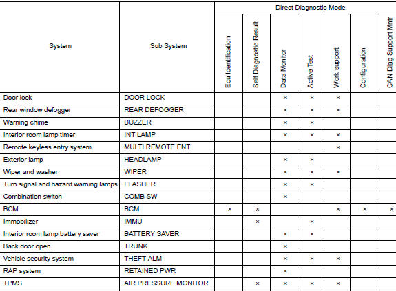
SYSTEM APPLICATION
BCM can perform the following functions.
RETAINED PWR
RETAINED PWR : CONSULT Function (BCM - RETAINED PWR)
DATA MONITOR
|
Monitor Item [Unit] |
Description |
| DOOR SW-DR [On/Off] | Indicates condition of front door switch LH. |
| DOOR SW-AS [On/Off] | Indicates condition of front door switch RH. |
 Diagnosis system (BCM) (with intelligent key system)
COMMON ITEM
COMMON ITEM : CONSULT Function (BCM - COMMON ITEM)
APPLICATION ITEM
CONSULT performs the following functions via CAN communication with BCM.
Direct Diagnostic Mode
De ...

Other materials:
System description
COMPONENT PARTS
Component Parts Location
No.
Component
Function
1
Combination meter
Combination meter transmits the vehicle speed signal to BCM via CAN
communication.
BCM also receives the vehicle speed signal from ABS actuator and
electric
...
Front passenger air bag module
Exploded View
Front passenger air bag module
Steering member
Removal and Installation
WARNING:
Before servicing the SRS, turn ignition switch OFF, disconnect
both battery terminals then wait at
least three minutes.
Always work from the side of air bag module. Do ...
S connector circuit
Description
The starter motor magnetic switch is supplied with power when the ignition
switch is turned to the START position
while the selector lever is in the P (Park) or N (Neutral) position.
Diagnosis Procedure
Regarding Wiring Diagram information, refer to STR-7, "Wiring Diagram" ...
