Nissan Rogue Service Manual: Parking brake switch signal circuit
Description
Transmits the parking brake switch signal to the combination meter.
Component Function Check
1.COMBINATION METER INPUT SIGNAL
- Start engine.
- Check "PKB SW" in "Data Monitor" while applying and releasing the parking brake.

Is the inspection result normal? YES >> Inspection End.
NO >> Refer to MWI-64, "Diagnosis Procedure".
Diagnosis Procedure
Regarding Wiring Diagram information, refer to MWI-32, "Wiring Diagram".
1.CHECK PARKING BRAKE SWITCH CIRCUIT
- Disconnect combination meter harness connector M76 and parking brake switch harness connector E52.
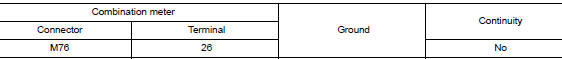
- Check continuity between combination meter harness connector M76 terminal 26 and parking brake switch harness connector E52 terminal 1.

- Check continuity between combination meter harness connector M76 terminal 26 and ground.
Is the inspection result normal? YES >> Inspection End.
NO >> Repair or replace harness or connector.
Component Inspection
1.CHECK PARKING BRAKE SWITCH
Check continuity between parking brake switch terminal 1 and switch case ground.
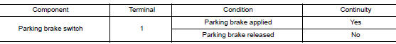
Is the inspection result normal? YES >> Inspection End.
NO >> Replace parking brake switch. Refer to PB-7, "Exploded View".
 Fuel level sensor signal circuit
Component Function Check
1.COMBINATION METER INPUT SIGNAL
Select "METER/M&A" on "CONSULT".
Using "FUEL METER" of "Data Monitor", compare ...
 Ambient sensor signal circuit
Description
It detects outside air temperature and converts it into a resistance value
which is then input into the combination
meter.
Diagnosis Procedure
Regarding Wiring Diagram information, r ...
Other materials:
The oil pressure warning continues displaying, or does
not display
Description
The low oil pressure warning message stays on when oil pressure is
normal.
The low oil pressure warning message stays off when oil pressure
is low.
Diagnosis Procedure
1.CHECK COMBINATION METER INPUT
Start the engine and select “METER/M&A” on CONSU ...
Terms
It is important to familiarize yourself with
the following terms before loading your
vehicle:
Curb Weight (actual weight of your
vehicle) - vehicle weight including:
standard and optional equipment, fluids,
emergency tools, and spare tire
assembly. This weight does not include
...
U0141 lost communication (BCM A)
DTC Description
DTC DETECTION LOGIC
DTC
CONSULT screen terms
(Trouble diagnosis content)
DTC detection condition
U0141
LOST COMM (BCM A)
(Lost Communication With Body Control Module
A)
When the ignition switch is turned ON, TCM continues no reception of
the ...
