Nissan Rogue Service Manual: Water outlet and water piping
Exploded View
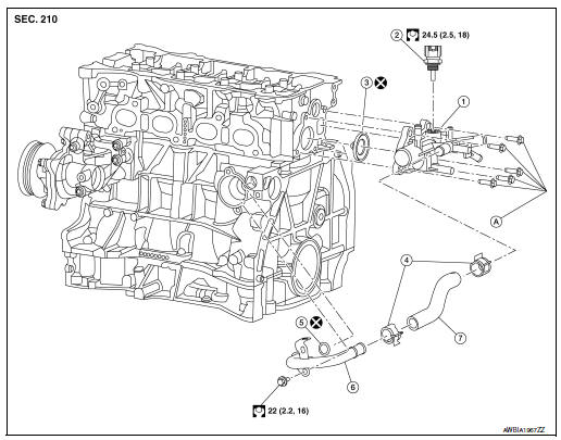
- Water outlet
- Water temperature sensor
- Water outlet O-ring
- Clamp
- Heater pipe O-ring
- Heater pipe
- Water hose
- Refer to INSTALLATION
Removal and Installation
WARNING: Do not remove the radiator cap when the engine is hot. Serious burns could occur from high-pressure engine coolant escaping from the radiator. Wrap a thick cloth around the cap. Slowly push down and turn it a quarter turn to allow built-up pressure to escape. Carefully remove the cap by pushing it down and turning it all the way.
NOTE: When removing components such as hoses, tubes/lines, etc., cap or plug openings to prevent fluid from spilling.
CAUTION: Perform when the engine cold.
REMOVAL
- Drain engine coolant from the radiator. Refer to CO-8, "Draining".
- Remove the upper radiator hose from water outlet.
- Remove resonator assembly. Refer to EM-24, "Exploded View".
- Remove battery tray. Refer to PG-75, "Exploded View".
- Remove ECM/TCM bracket, (if necessary).
- Disconnect harness connector from water temperature sensor.
- Remove water temperature sensor from water outlet, (if necessary).
- Remove heater hoses from water outlet.
NOTE: Note location of heater hoses prior to removal to serve as an installation aid.
- Remove water hoses from water outlet.
NOTE: Note location of heater hoses prior to removal to serve as an installation aid.
- Remove water hoses from electric throttle control actuator.
- Remove the water outlet.
INSTALLATION
- Tighten water outlet bolts in sequence to specification.
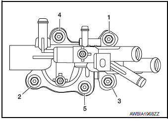
22 N·m (2.2 kg-m, 16 ft-lb)
Installation of remaining components is in the reverse order of removal.
CAUTION:
- Do not reuse heater pipe O-ring.
- Do not reuse water outlet O-ring.
- To install heater pipe, first apply a mild soap to the O-ring and quickly insert the heater pipe into the housing.
- Do not spill coolant in engine compartment. Use a shop cloth to absorb coolant.
After installation, refill coolant and check for leaks. Refer to CO-9, "Refilling" and CO-8, "Inspection".
 Thermostat and water control
valve
Thermostat and water control
valve
Exploded View
Water inlet
Thermostat
Rubber ring
To radiator hose (lower)
NOTE:
When removing components such as hoses, tubes/lines, etc., cap or plug opening ...
 Service data and specifications (SDS)
Periodical Maintenance Specification
ENGINE COOLANT CAPACITY (APPROXIMATE)
Radiator
Thermostat
...
Other materials:
System description
SYSTEM
System Description
SYSTEM DIAGRAM
SYSTEM DESCRIPTION
The BCM has a CAN gateway function.
The BCM communicates between two CAN communication circuits.
The BCM selects and transmits only necessary information.
DIAGNOSIS SYSTEM (CAN GATEWAY)
CONSULT Function
...
Maintenance precautions
When performing any inspection or maintenance
work on your vehicle, always take care to prevent
serious accidental injury to yourself or damage to
the vehicle. The following are general precautions
which should be closely observed.
WARNING
Park the vehicle on a level surface, a ...
DTC/circuit diagnosis
U1000 CAN COMM CIRCUIT
Description
CAN (Controller Area Network) is a serial communication system for real time
application. It is an on-vehicle
multiplex communication system with high data communication speed and excellent
error detection ability.
Many electronic control units are equipp ...
