
Nissan Rogue Service Manual: Vacuum lines
Exploded View
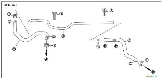
- Clamp
- Vacuum hose
- Vacuum tube
- Clip
- Vacuum hose
- To intake manifold
- To brake booster
- Paint mark
- Stamp indicating engine direction
Removal and Installation
REMOVAL
- Remove the cowl top. Refer to EXT-25, "Removal and Installation".
- Remove the air duct assembly to the electric throttle control actuator. Refer to EM-24, "Exploded View".
- Disconnect the vacuum hose from the engine intake manifold.
- Disconnect the vacuum hose from the brake booster.
- Disconnect the vacuum hose from the clip.
- Remove the vacuum hoses.
INSPECTION AFTER REMOVAL
Visual Inspection
Check for correct installation, damage and deterioration of the vacuum hoses and pipe.
INSTALLATION
Installation is in the reverse order of removal.
CAUTION:
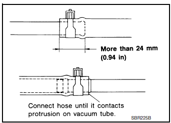
- Insert the vacuum pipe into the vacuum hose at least 24 mm (0.94 in) as shown.
- Do not use lubricating oil during installation.
 Brake booster
Exploded View
Spacer
Gasket
Brake booster
Check valve
Reservoir tank
Brake fluid level sensor
Brake booster pressure sensor
Removal and installation
REMOVAL
...
 Front disc brake
BRAKE PAD (1 PISTON TYPE)
BRAKE PAD (1 PISTON TYPE) : Exploded View
Torque member
Bushing
Piston boot
Slide pin boot
Slide pin
Piston
Piston seal
Brake caliper ...
Other materials:
Front regulator
Exploded View
Front door panel
Front door regulator
Front door power window motor
Front door glass run rear
Front door glass run front
Front door glass
Front door glass rubber run
Removal and Installation
REMOVAL
Remove the front door finisher. Refer to INT-15, ...
System description
COMPONENT PARTS
Component Parts Location
Right rear wheel area
Instrument panel
Engine compartment
Left side of instrument panel (view
with trim panel removed)
No.
Part
Function
1
Optical sensor
Refer to EXL-10, "Optical Sensor" ...
Adjustment of steering angle sensor neutral position
Description
Refer to the table below to determine if adjustment of steering angle sensor
neutral position is required.
Work Procedure
ADJUSTMENT OF STEERING ANGLE SENSOR NEUTRAL POSITION
CAUTION:
To adjust neutral position of steering angle sensor, make sure to use CONSULT.
(Adjustment ...
