Nissan Rogue Service Manual: Unit removal and installation
FRONT SUSPENSION MEMBER
Exploded View
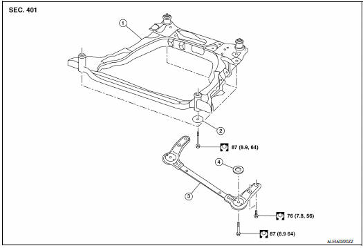
- Front suspension member
- Strut mounting bearing
- Rebound stopper insulator
- Rebound stopper
Removal and Installation
REMOVAL
- Remove the wheel and tire using power tool. Refer to WT-60, "Removal and Installation".
- Remove side under cover. Refer to EXT-37, "ENGINE UNDER COVER : Removal and Installation".
- Remove the bolt and separate the front wheel sensor from the steering knuckle. Separate the harness from the brackets and position aside. Refer to BRC-132, "FRONT WHEEL SENSOR : Exploded View".
CAUTION:
- Failure to separate the front wheel sensor from the steering knuckle may result in damage to the front wheel sensor.
- Pull out the front wheel sensor, being careful to turn it as little as possible. Do not pull on wheel sensor harness.
- Remove the nut and separate the stabilizer connecting rod from the strut bracket.
- Remove the cotter pin and nut, and separate the outer socket from the steering knuckle.
- Remove the bolt and separate steering column yoke from steering gear. Refer to ST-12, "Exploded View".
- Remove transverse link from steering knuckle. Refer to FAX-9, "Exploded View" (FWD), FAX-40, "Exploded View" (AWD).
- Remove rear torque rod. Refer to EM-81, "Exploded View".
- Set suitable jack front suspension member.
- Remove front suspension member stay from vehicle.
- Remove bolts and nuts of front suspension member.
- Gradually lower jack to remove front suspension assembly from
vehicle.
CAUTION: Secure suspension assembly to suitable jack while removing it.
- Remove bolts and nuts, and then remove transverse link, stabilizer bar from front suspension member.
INSTALLATION
Installation is in the reverse order of removal.
- Install the suspension member bolts in the order shown.
1-2 temporary tightening
3-5 torque to specification Refer to FSU-20, "Exploded View".
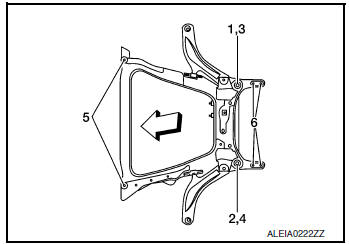
 : Front
- Perform final tightening of installation position between front suspension member and transverse links (rubber bushing) under unladen condition with tires on level ground.
- Check wheel sensor harness for proper connection. Refer to BRC- 132, "FRONT WHEEL SENSOR : Exploded View".
Inspection
INSPECTION AFTER REMOVAL
Check the front suspension member for significant deformation, cracks, or damages. Replace it if necessary.
INSPECTION AFTER INSTALLATION
Check wheel alignment. Refer to FSU-7, "Inspection".
 Removal and installation
FRONT COIL SPRING AND STRUT
Exploded View
Strut mount insulator
Rotary stop
Front spring upper rubber seat
Front suspension bound bumper
Front spring
Front spring lower ru ...
 Unit disassembly and assembly
FRONT COIL SPRING AND STRUT
Exploded View
Strut mount insulator
Rotary Stop
Front spring upper rubber seat
Front suspension bound bumper
Front spring
Front spring lo ...
Other materials:
Interior room lamp control system
Wiring Diagram
...
P0448 EVAP canister vent control valve
DTC Description
DTC DETECTION LOGIC
DTC No.
CONSULT screen terms
(Trouble diagnosis content)
DTC detecting condition
P0448
VENT CONTROL VALVE
(Evaporative emission system vent control
circuit shorted)
EVAP canister vent control valve remains closed under specif ...
Engine compartment
CAUTIONNever use a fuse of a higher or lower
amperage rating than specified on the
fuse box cover. This could damage the
electrical system or cause a fire.
Two types of fuses are used. Type A is used in
the fuse boxes in the engine compartment. Type
B is used in the passe ...
