Nissan Rogue Service Manual: Unit disassembly and assembly
STEERING GEAR AND LINKAGE
Exploded View
DISASSEMBLY AND ASSEMBLY
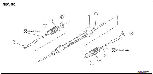
- Steering gear
- Inner boot clamp
- Boot
- Outer boot clamp
- Outer socket
Disassembly and Assembly
DISASSEMBLY
- Remove outer socket lock nut and remove outer socket.
- Remove inner and outer boot clamps and remove boot.
ASSEMBLY
- Apply recommended grease to inner socket.
- Install boot to steering gear.
- Install inner boot clamp (1) to boot and secure using Tool (A).
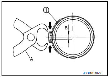
Tool number : (KV40107300) ( — )
CAUTION:
- Install inner boot clamp (1) securely to boot groove, and crimp it so as to have clearance (B) of 3 mm (0.12 in) or less as shown.
- Inspect boot clamps and replace as necessary.
- Install outer boot clamp to boot.
CAUTION: Inspect boot and replace as necessary.
- Install outer socket (3) and lock nut (2) to achieve length (A).
Check that inner socket (1) and outer socket (3) measure to standard length (B), then tighten lock nut (2) to the specified torque. Check length again after tightening lock nut (2).
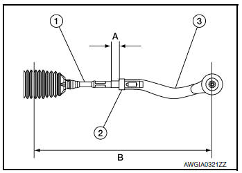
B : Refer to ST-19, "Steering Gear".
CAUTION:
- Adjust toe-in after this procedure. Length achieved after toe-in adjustment is not necessary the value above.
- When tightening lock nut, be sure to fix outer socket with a wrench or equivalent to prevent ball joint from getting contact with knuckle.
 Steering gear and linkage
Exploded View
REMOVAL AND INSTALLATION
Cotter pin
Steering gear
Heat shiel
Removal and Installation
REMOVAL
Set the front wheels and tires to the straight-ahea ...
 Service data and specifications (SDS)
Steering Wheel
Steering Angle
Steering Column
STEERING COLUMN LENGTH
STEERING COLUMN ROTATING TORQUE
TILT MECHANISM OPERATING RANGE
Steering Gear
STEERING OUTER SOCKET AND I ...
Other materials:
Inside mirror
Exploded View
MANUAL ANTI-DAZZLING
Windshield glass
Mirror base
Inside mirror
AUTO ANTI-DAZZLING
Windshield glass
Mirror base
Inside mirror
Inside mirror finisher
Harness connector
Bolt
Removal and Installation
MANUAL ANTI-DAZZLING
Removal ...
Diagnosis system (IPDM E/R)
CONSULT Function (IPDM E/R)
APPLICATION ITEM
CONSULT performs the following functions via CAN communication with IPDM E/R.
Direct Diagnostic Mode
Description
Ecu Identification
The IPDM E/R part number is displayed.
Self Diagnostic Result
The IPDM E/R sel ...
U1050, U1051 LIN communication
DTC Description
DTC DETECTION LOGIC
DTC No.
CONSULT screen terms
(Trouble diagnosis content)
DTC detecting condition
U1050
LIN COMMUNICATION
[LIN (Local Interconnect Network) communication)]
ECM detects LIN communication error.
U1051
POSSIBLE CAUSE
...
