Nissan Rogue Service Manual: System
WARNING CHIME SYSTEM
WARNING CHIME SYSTEM : System Description
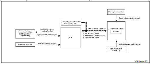
SYSTEM DIAGRAM (WITH INTELLIGENT KEY SYSTEM)
SYSTEM DIAGRAM (WITHOUT INTELLIGENT KEY SYSTEM)
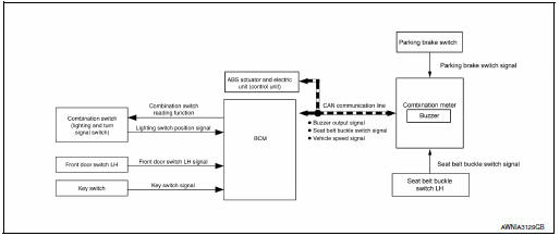
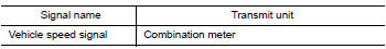
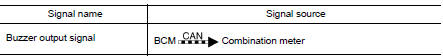
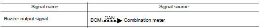
COMBINATION METER INPUT/OUTPUT SIGNAL (CAN COMMUNICATION SIGNAL)
Input signal
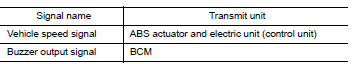
Output signal
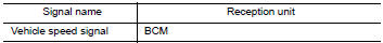
BCM INPUT/OUTPUT SIGNAL (CAN COMMUNICATION SIGNAL)
Input signal
Output signal

DESCRIPTION
Combination Meter
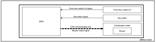
The combination meter sounds the alarm buzzer installed in the combination meter when receiving the buzzer output signal transmitted from each unit.
BCM
BCM receives signals from various units and transmits a buzzer output signal to the combination meter via CAN communication if it judges that the warning buzzer should be activated.
WARNING CHIME FUNCTION LIST

WARNING CHIME SYSTEM : Fail-safe
The combination meter activates the fail-safe control if CAN communication with each unit is malfunctioning.

LIGHT REMINDER WARNING CHIME
LIGHT REMINDER WARNING CHIME : Light Reminder Warning
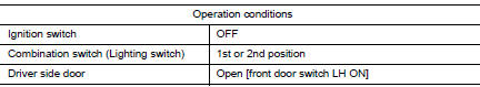
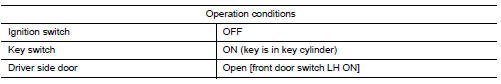
WARNING CHIME OPERATION CONDITIONS
If all of the following conditions are fulfilled.
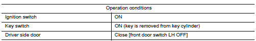
WARNING CHIME CANCEL CONDITIONS
Warning is canceled if any of the following conditions is fulfilled.

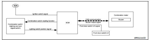
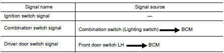
SIGNAL PATH
- BCM requires warning chime output to combination meter when it judges light reminder warning chime is necessary from signals below.
- Combination meter sounds integrated buzzer, following the warning chime output requirement (below signal) from BCM.
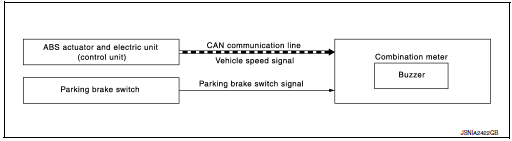
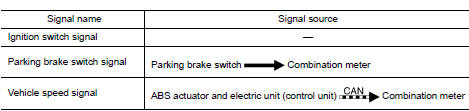
PARKING BRAKE RELEASE WARNING CHIME
PARKING BRAKE RELEASE WARNING CHIME : Parking Brake Release Warning Chime
SYSTEM DIAGRAM
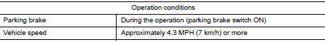
WARNING OPERATION CONDITIONS
If all of the following conditions are fulfilled

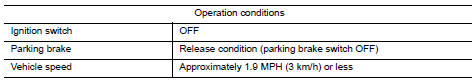
WARNING CANCEL CONDITIONS
Warning is canceled if any of the following conditions are fulfilled.
SIGNAL PATH
Combination meter sounds integrated buzzer when it judges that parking brake release warning chime is necessary from signals below.
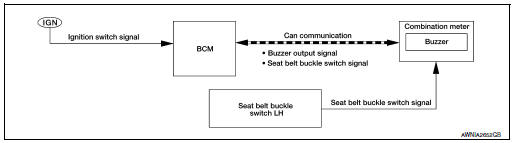
SEAT BELT REMINDER WARNING CHIME
SEAT BELT REMINDER WARNING CHIME : Seat belt Warning
SYSTEM DIAGRAM
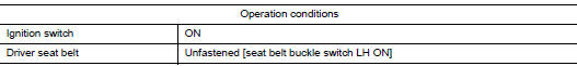
WARNING OPERATION CONDITIONS
If all of the following conditions are fulfilled.
WARNING CANCEL CONDITIONS
Warning is canceled if any of the following conditions is fulfilled.

SIGNAL PATH
- BCM requires warning chime output to combination meter when it judges seat belt warning chime is necessary from signals below.
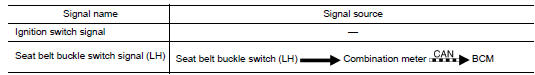
- Combination meter sounds integrated buzzer, following the warning chime output requirement (below signal) from BCM.
KEY WARNING CHIME
KEY WARNING CHIME : Key Warning Chime
SYSTEM DIAGRAM
WARNING CHIME OPERATION CONDITIONS
If all of the following conditions are fulfilled.
WARNING CHIME CANCEL CONDITIONS
Warning is canceled if any of the following conditions is fulfilled.
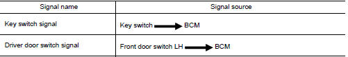
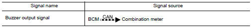
SIGNAL PATH
- BCM detects key inserted into the ignition switch, and sends key warning signal to combination meter with CAN communication line.

- Combination meter sounds integrated buzzer, when it receives a buzzer output signal from BCM.
 Component parts
Component Parts Location
No.
Component
Function
1
Key switch
Transmits the key switch signal to the BCM.
Refer to SEC-115, "Component Parts Locat ...
 Diagnosis system (combination meter)
Description
COMBINATION METER SELF-DIAGNOSIS MODE
The following meter functions can be checked during Combination Meter
Self-Diagnosis Mode:
Pointer sweep of speedometer, tachometer and ...
Other materials:
CAN system (type 6)
MAIN LINE BETWEEN IPDM-E AND DLC CIRCUIT
Diagnosis Procedure
1.CHECK CONNECTOR
Turn the ignition switch OFF.
Disconnect the battery cable from the negative terminal.
Check the following terminals and connectors for damage, bend and
loose connection (connector side
an ...
Precaution
Precaution for Supplemental Restraint System
(SRS) "AIR BAG" and "SEAT BELT PRE-TENSIONER"
The Supplemental Restraint System such as ÔÇťAIR BAGÔÇŁ and ÔÇťSEAT BELT PRE-TENSIONERÔÇŁ,
used along
with a front seat belt, helps to reduce the risk or severity of injury to the
dr ...
Brake pedal position switch
Component Function Check
1.CHECK BRAKE PEDAL POSITION SWITCH FUNCTION
With CONSULT
Turn ignition switch ON.
Select ÔÇťBRAKE SW1ÔÇŁ in ÔÇťDATA MONITORÔÇŁ mode with CONSULT.
Check ÔÇťBRAKE SW1ÔÇŁ indication as per the following conditions.
Without CONSULT
...
