Nissan Rogue Service Manual: Tire pressure sensor
Exploded View
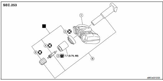
- Tire pressure sensor
- O-ring
- Valve stem nut
- Valve core
- Valve cap
- Valve stem assembly
 : Parts that are replaced as a
set when the tire is replaced.
: Parts that are replaced as a
set when the tire is replaced.
Removal and Installation
REMOVAL
- Remove wheel and tire using power tool.
- Remove valve cap and valve core to deflate the tire.
NOTE: If the tire is to be reused, apply a matching mark on the tire in line with the position of the valve stem assembly for the purpose of wheel and tire balance adjustment after installation.
- Remove the valve stem nut and allow tire pressure sensor (1) to fall into tire.
- Lubricate the tire outside bead well with a suitable non-silicone lubricant, and remove outside of tire from the wheel. Reach inside the tire and remove the tire pressure sensor.
CAUTION:
- Do not use silicone lubricant. Use of silicone lubricant will deteriorate the tire and wheel.
- Be sure not to damage the wheel or tire pressure sensor.
- Do not allow lubricant to make contact with tire pressure sensor.
- Lubricate the tire inside bead well with a suitable non-silicone lubricant, and remove inside of tire from the wheel.
CAUTION:
- Do not use silicone lubricant. Use of silicone lubricant will deteriorate the tire and wheel.
- Be sure not to damage the wheel.
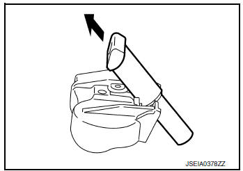
- Remove the valve stem from the tire pressure sensor as shown.
INSTALLATION
- Apply a suitable non-silicone lubricant to the tire inside bead.
CAUTION:
- Do not use silicone lubricant. Use of silicone lubricant will deteriorate the tire and wheel.
- Do not drop or strike the tire pressure sensor. Replace the tire pressure sensor if it has been dropped from higher than one meter.
- Install the tire inside bead (1) onto the wheel (2) in the position shown.
- Install the valve stem to the tire pressure sensor.
- Install the O-ring to the tire pressure sensor.
CAUTION:
- Do not reuse O-ring
- Insert O-ring to the base of the tire pressure sensor.
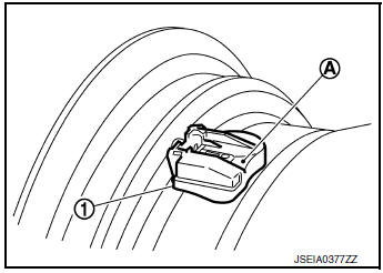
- The base of the valve stem (A) must be positioned in the groove of the metal plate as shown.

- Install tire pressure sensor (1) to wheel while pressing at position (A).
CAUTION:
- Check that O-ring contacts horizontally with wheel.
- Check that the base of the valve stem is positioned in the groove of the metal plate.
- Be sure that no burrs exist in the valve stem hole of the wheel.
- Install and tighten the valve stem nut to the specified torque.
Valve stem nut tightening torque : WT-61, "Exploded View"
CAUTION: Do not use power tool for installation.
- Place wheel on turntable of tire machine. Ensure that tire
pressure
sensor (1) is 270 degrees from mounting/dismounting head
(2).
NOTE: Do not touch tire pressure sensor with mounting head.
- Apply a suitable non-silicone lubricant to the tire outside bead.
CAUTION:
- Do not use silicone lubricant. Use of silicone lubricant will deteriorate the tire and wheel.
- Do not allow lubricant to make contact with tire pressure sensor.
- Install the tire outside bead onto the wheel as normal.
NOTE: If the tire is being reused, align the matching mark applied on the tire with the position of the valve stem assembly for the purpose of wheel and tire balance adjustment after installation. Make sure that the tire does not rotate relative to wheel.
- Install the valve core and inflate tire.
CAUTION: Do not reuse valve core.
- Install the valve cap.
CAUTION: Do not reuse valve cap.
- Balance the wheel and tire. Refer to WT-57, "Adjustment".
- Install wheel and tire in appropriate wheel position on vehicle.
Refer to WT-60, "Removal and Installation".
NOTE: If replacing the tire pressure sensor, then tire pressure sensor wake up operation must be performed.
Refer to WT-21, "Work Procedure".
- Adjust neutral position of steering angle sensor. Refer to BRC-70, "Work Procedure".
- . Perform the ID registration procedure. Refer to WT-21, "Work Procedure".
Remote keyless entry receiver
Removal and Installation
The Remote Keyless Entry Reciever is an integral part of the BCM (BODY CONTROL MODULE). Refer to BCS-75, "Removal and Installation" (WITH INTELLIGENT KEY SYSTEM) or BCS-135, "Removal and Installation"( WITHOUT INTELLIGENT KEY SYSTEM).
 Wheel and tire
Exploded View
Wheel and tire
Wheel nut
Removal and Installation
REMOVAL
Remove wheel nuts using power tool.
Remove wheel and tire.
INSTALLATION
Installation ...
 Service data and specifications (sds)
Wheel
ALUMINUM WHEEL
STEEL WHEEL
Tire Air Pressure
...
Other materials:
Precaution
Precaution for Supplemental Restraint System (SRS) "AIR BAG" and "SEAT
BELT
PRE-TENSIONER"
The Supplemental Restraint System such as “AIR BAG” and “SEAT BELT PRE-TENSIONER”,
used along
with a front seat belt, helps to reduce the risk or severity of injury to the
...
Power supply and ground circuit
Diagnosis Procedure
1.CHECK FUSE
Check that the following fuse is not fusing.
Is the fuse fusing?
YES >> Replace the fuse after repairing the applicable circuit.
NO >> GO TO 2.
2.CHECK GROUND CONNECTION
Turn ignition switch OFF.
Check ground connection E9 or E ...
How to use the vehicle information display
The vehicle information display can be changed
using the buttons and ENTER located
on
the steering wheel.
— navigate through the
items in vehicle
information
ENTER — change or select an item in the
vehicle information display
— select/enter the
Vehicle i ...
