Nissan Rogue Service Manual: Component parts
Component Parts Location
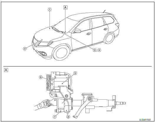
- Steering column assembly
| No. | Component | Function |
| 1 | ABS actuator and electric unit (control unit) |
|
| 2 | ECM |
|
| 3 | Combination meter |
|
|
||
| 4 | EPS warning lamp | STC-7, "EPS SYSTEM : System Description" |
| 5 | EPS motor | STC-6, "EPS Motor, Torque Sensor, Reduction Gear" |
| 6 | EPS control unit | STC-6, "EPS Control Unit" |
| 7 | Reduction gear | STC-6, "EPS Motor, Torque Sensor, Reduction Gear" |
| 8 | Torque sensor | STC-6, "EPS Motor, Torque Sensor, Reduction Gear" |
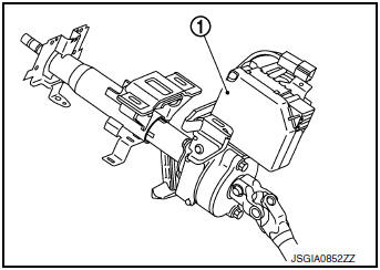
EPS Control Unit
- EPS control unit (1) is installed to steering column assembly.
- EPS control unit performs an arithmetical operation on data, such as steering wheel turning force (sensor signal) from the torque sensor, vehicle speed signal, etc. Then it generates an optimum assist torque signal to the EPS motor according to the driving condition.
- EPS control unit decreases the output signal to EPS motor during continuous extreme use of the power steering function (e.g., full steering) for protection of the EPS motor and EPS control unit (Overload protection control).
EPS Motor, Torque Sensor, Reduction Gear
EPS motor (1), torque sensor (2) and reduction gear (3) are installed to steering column assembly.
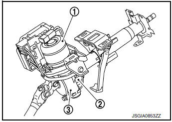
EPS MOTOR
EPS motor provides assist torque in proportion to the control signal from the EPS control unit.
TORQUE SENSOR
Torque sensor detects the steering torque and transmits the signal to the EPS control unit.
REDUCTION GEAR
Reduction gear increases the assist torque provided from the EPS motor, and outputs to the column shaft.

 System
EPS SYSTEM
EPS SYSTEM : System Description
SYSTEM DIAGRAM
INPUT/OUTPUT SIGNAL
Communicates the signal from each control unit via CAN communication.
Control unit
Signal statu ...
Other materials:
P2118 throttle control motor
DTC Description
DTC DETECTION LOGIC
DTC No.
CONSULT screen terms
(Trouble diagnosis content)
DTC detecting condition
P2118
ETC MOT-B1
(Throttle actuator control motor current
range/performance)
ECM detects short in both circuits between ECM and throttle control ...
Power supply and ground circuit
Diagnosis Procedure
1.CHECK FUSE
Check that the following fuse is not fusing.
Is the fuse fusing?
YES >> Replace the fuse after repairing the applicable circuit.
NO >> GO TO 2.
2.CHECK GROUND CONNECTION
Turn ignition switch OFF.
Check ground connection E9 or E ...
Diagnosis system (BCM) (with intelligent key system)
COMMON ITEM
COMMON ITEM : CONSULT Function (BCM - COMMON ITEM)
APPLICATION ITEM
CONSULT performs the following functions via CAN communication with BCM.
Direct Diagnostic Mode
Description
Ecu Identification
The BCM part number is displayed.
Self Diagnostic ...
