Nissan Rogue Service Manual: System description
COMPONENT PARTS
Component Parts Location
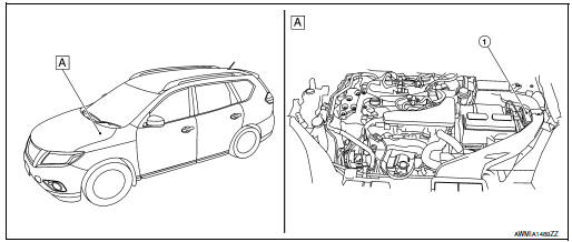
- IPDM E/R
- Engine compartment (LH)
SYSTEM
RELAY CONTROL SYSTEM
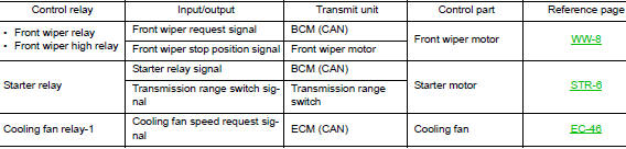
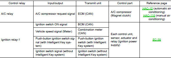
RELAY CONTROL SYSTEM : System Description
SYSTEM DIAGRAM
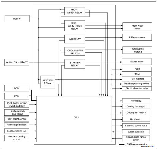
DESCRIPTION
IPDM E/R activates the internal control circuit to perform the relay ON-OFF control according to the input signals from various sensors and the request signals received from control units via CAN communication.
CAUTION: IPDM E/R integrated relays cannot be removed.
RELAY CONTROL SYSTEM : Fail-safe
CAN COMMUNICATION CONTROL
When CAN communication with ECM and BCM is impossible, IPDM E/R performs fail-safe control. After CAN communication recovers normally, it also returns to normal control.
If No CAN Communication Is Available With ECM
|
Control part |
Fail-safe operation |
| Cooling fan |
|
| A/C compressor | A/C relay OFF |
If No CAN Communication Is Available With BCM
|
Control part |
Fail-safe operation |
| Front wiper motor |
|
| Horn | Horn OFF |
| Ignition relay-1 | The status just before activation of fail-safe is maintained. |
| Starter motor | Starter relay OFF |
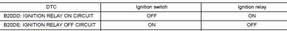
IGNITION RELAY MALFUNCTION DETECTION FUNCTION
- IPDM E/R monitors the voltage at the contact circuit and excitation coil circuit of the ignition relay-1 inside it.
- IPDM E/R judges the ignition relay-1 error if the voltage differs between the contact circuit and the excitation coil circuit.
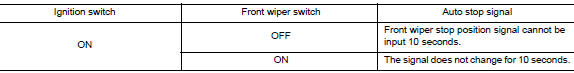
FRONT WIPER CONTROL
IPDM E/R detects front wiper stop position by a front wiper auto stop signal.
When a front wiper auto stop signal is in the conditions listed below, IPDM E/R stops power supply to wiper after repeating a front wiper 10 second activation and 20 second stop five times.
NOTE: This operation status can be confirmed on the IPDM E/R “Data Monitor” that displays “BLOCK” for the item “WIP PROT” while the wiper is stopped.
STARTER MOTOR PROTECTION FUNCTION
IPDM E/R turns OFF the starter relay to protect the starter motor when the starter relay remains active for 90 seconds.
SMART FIELD-EFFECT TRANSISTOR (FET)
SMART FIELD-EFFECT TRANSISTOR (FET) : System Description
A smart Field-Effect Transistor (FET) is a transistor used to monitor and control current flow on module outputs.
The IPDM E/R uses a smart FET protection strategy to prevent module damage in the event of excessive current flow. The smart FET protection strategy monitors its outputs for excessive current, and when a fault occurs, shuts down the output and records a DTC.
POWER CONSUMPTION CONTROL SYSTEM
POWER CONSUMPTION CONTROL SYSTEM : System Description
SYSTEM DIAGRAM
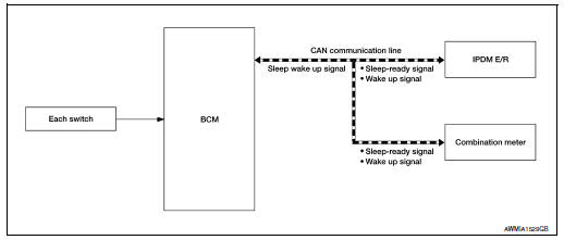
DESCRIPTION
Outline
- IPDM E/R incorporates a power consumption control function that reduces the power consumption according to the vehicle status.
- IPDM E/R changes its status (control mode) with the sleep wake up signal received from BCM via CAN communication.
Normal mode (wake-up)
- CAN communication is normally performed with other control units.
- Individual unit control by IPDM E/R is normally performed.
Low power consumption mode (sleep)
- Low power consumption control is active.
- CAN transmission is stopped.
Sleep Mode Activation
- IPDM E/R judges that the sleep-ready conditions are fulfilled when the ignition switch is OFF and none of the conditions below are present. Then it transmits a sleep-ready signal (ready) to BCM via CAN communication.
- Outputting signals to actuators
- Switches or relays operating
- Output requests are being received from control units via CAN communication.
- IPDM E/R stops CAN communication and enters the low power consumption mode when it receives a sleep wake up signal (sleep) from BCM and the sleep-ready conditions are fulfilled.
Wake-up Operation
- IPDM E/R changes from the low power consumption mode to the normal mode when it receives a sleep wake-up signal (wake up) from BCM or any of the following conditions is fulfilled. In addition, it transmits a sleep-ready signal (not-ready) to BCM via CAN communication to report the CAN communication start.
- Ignition switch ON
- An output request is received from a control unit via CAN communication.
DIAGNOSIS SYSTEM (IPDM E/R)
CONSULT Function (IPDM E/R)
APPLICATION ITEM
CONSULT performs the following functions via CAN communication with IPDM E/R.
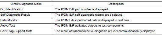
ECU IDENTIFICATION
The IPDM E/R part number is displayed.
SELF DIAGNOSTIC RESULT
Refer to PCS-20, "DTC Index".
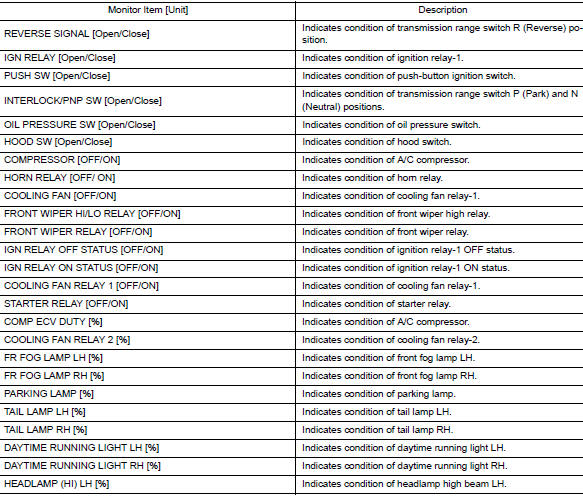
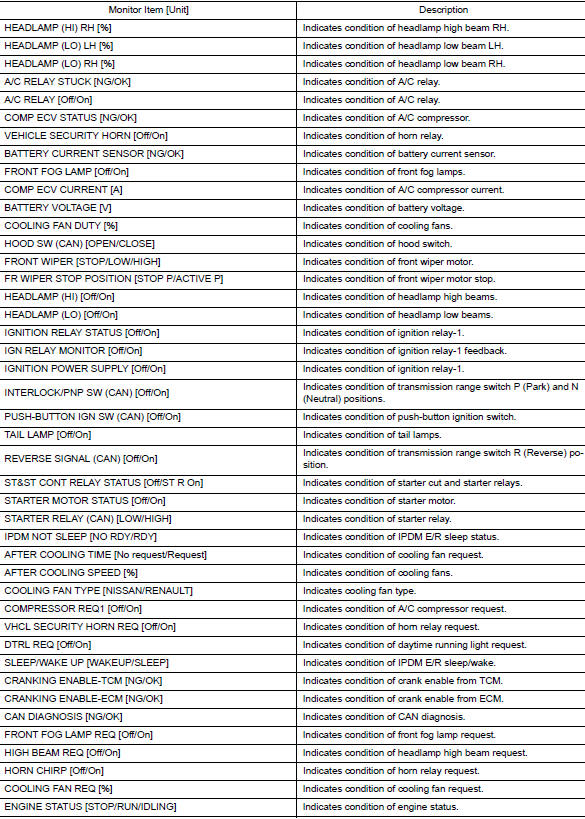
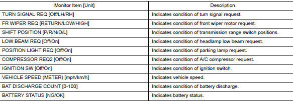
DATA MONITOR
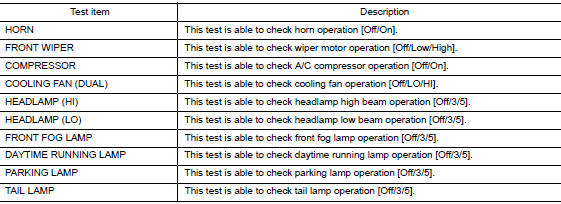
ACTIVE TEST
CAN DIAG SUPPORT MNTR
Refer to LAN-14, "CAN Diagnostic Support Monitor".
 Precaution
Precaution for Supplemental Restraint System (SRS) "AIR BAG" and "SEAT
BELT
PRE-TENSIONER"
The Supplemental Restraint System such as “AIR BAG” and “SEAT BELT PRE-TENSIONE ...
 ECU diagnosis information
IPDM E/R (INTELLIGENT POWER DISTRIBUTION MODULE ENGINE
ROOM)
Reference Value
VALUES ON THE DIAGNOSIS TOOL
TERMINAL LAYOUT
PHYSICAL VALUES
1: With Intelligent ...
Other materials:
U0155 lost communication (IPC)
DTC Description
DTC DETECTION LOGIC
DTC
CONSULT screen terms
(Trouble diagnosis content)
DTC detection condition
U0155
LOST COMM (IPC)
[Lost Communication With Instrument Panel
Cluster (IPC) Control Module]
When the ignition switch is ON, TCM is unable to recei ...
P0643 sensor power supply
Description
ECM supplies a voltage of 5 V to some of the sensors systematically divided
into 2 groups, respectively.
Accordingly, when a short circuit develops in a sensor power source, a
malfunction may occur simultaneously
in the sensors belonging to the same group as the short-circuited ...
P1574 ASCD vehicle speed sensor
Description
The ECM receives two vehicle speed sensor signals via CAN communication line.
One is sent from combination
meter, and the other is from TCM (Transmission control module). The ECM uses
these signals for ASCD
control. Refer to EC-47, "AUTOMATIC SPEED CONTROL DEVICE (ASCD) : Sys ...
