Nissan Rogue Service Manual: System
EPS SYSTEM
EPS SYSTEM : System Description
SYSTEM DIAGRAM
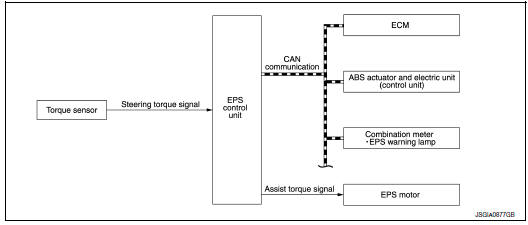
INPUT/OUTPUT SIGNAL
Communicates the signal from each control unit via CAN communication.
|
Control unit |
Signal status |
| ECM |
|
| ABS actuator and electric unit (control unit) |
|
| Combination meter |
|
DESCRIPTION
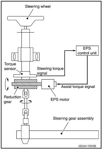
- EPS control unit performs an arithmetical operation on data, such as steering wheel turning force (sensor signal) from the torque sensor, vehicle speed signal, etc. Then it generates an optimum assist torque signal to the EPS motor according to the driving condition.
- In case of an error in the electrical system, the fail-safe function stops output signals to the EPS motor. Refer to STC-8, "EPS SYSTEM : Fail-Safe".
- EPS control unit decreases the output signal to EPS motor during extreme use of the power steering function (e.g., full steering) for protection of the EPS motor and EPS control unit (Overload protection control).
- Extensive steering at low speed will cause the EPS control unit
and EPS motor to heat up. Once temperature reaches the critical
point, the EPS control unit will reduce current to reduce heat up.
System will recover as temperature lowers (reduced or no assistance).
EPS WARNING LAMP INDICATION
- Turns ON when there is a malfunction in the EPS system. If ON, fail-safe mode is engaged and the system enters a manual steering state (turning force at steering wheel becomes heavy).
- Also turns ON when ignition switch is turned ON, for purpose of lamp check. Turns OFF after the engine starts, if system is normal.
|
Condition |
EPS warning lamp |
| Ignition switch ON. (Lamp check) | ON |
| Engine running. | OFF |
| EPS system malfunction [Other diagnostic item] | ON |
CAUTION: EPS warning lamp also turns ON due to data reception error, CAN communication error etc.
EPS SYSTEM : Fail-Safe
- If any malfunction occurs in the system and the control unit detects the malfunction, the EPS warning lamp in the combination meter turns ON to indicate system malfunction.
- When EPS warning lamp is ON, the system enters into a manual steering state. (turning force at steering wheel becomes heavy.)
- Under abnormal vehicle speed signal conditions, vehicle speed is judged as constant
EPS SYSTEM : Protection Function
While overload protection control is activated, assist torque gradually decreases and the steering wheel turning force becomes heavy. Assist torque returns to normal if the steering wheel is not turned for a while.
 Component parts
Component Parts Location
Steering column assembly
No.
Component
Function
1
ABS actuator and electric unit (control unit)
Transmits the following signal ...
 Diagnosis system (EPS control unit)
CONSULT Function
FUNCTION
CONSULT can display each diagnostic item using the diagnostic test modes
shown following
Diagnostic test mode
Function
ECU identification
The p ...
Other materials:
Brake fluid
Inspection
BRAKE FLUID LEVEL
Make sure that the brake fluid level in the reservoir tank is
between
the MAX and MIN lines.
Visually check around the reservoir tank for brake fluid leakage.
If the brake fluid level is excessively low, check the brake
system
for lea ...
Symptom diagnosis
COMBINATION SWITCH SYSTEM SYMPTOMS
Symptom Table
Perform the data monitor of CONSULT to check for any malfunctioning
item.
Check the malfunction combinations.
Identify the malfunctioning part from the agreed combination and repair
or replace the part.
NORMAL OPERATING C ...
Air breather
Exploded View
Air breather
Air breather hose
Air breather tube
Transaxle assembly
: Vehicle front
Removal and Installation
REMOVAL
Remove air cleaner and air duct. Refer to EM-24, "Removal and
Installation".
Remove air breather hose from transaxle a ...
