Nissan Rogue Service Manual: Basic inspection
DIAGNOSIS AND REPAIR WORKFLOW
Work Flow
OVERALL SEQUENCE
DETAILED FLOW
1.INTERVIEW CUSTOMER
Interview the customer to obtain as much information as possible about the conditions and environment under which the malfunction occurred.
>> GO TO 2.
2.SYMPTOM CHECK
Verify symptoms.
>> GO TO 3.
3.CHECK FOR DTCS
 With CONSULT
- Turn ignition switch ON.
- Select “Self Diagnostic Result” mode of “HVAC” using CONSULT.
- Check DTC.
Is any DTC detected? YES >> GO TO 4.
NO >> GO TO 5.
4.PERFORM DTC DIAGNOSTIC PROCEDURE
Perform the diagnostic procedure for the detected DTC. Refer to HAC-134, "DTC Inspection Priority Chart".
>> GO TO 7.
5.OPERATION CHECK
Perform the operation check. Refer to HAC-148, "Work Procedure".
>> GO TO 6.
6.SYMPTOM DIAGNOSIS
Check the symptom diagnosis table. Refer to HAC-174, "Symptom Table".
>> GO TO 8.
7.VERIFY REPAIR.
 With CONSULT
- Turn ignition switch ON.
- Select “Self Diagnostic Result” mode of “HVAC” using CONSULT.
- Check DTC.
Is any DTC detected? YES >> GO TO 4.
NO >> GO TO 8.
8.PERFORM FINAL OPERATION CHECK
Perform the operation check. Refer to HAC-148, "Work Procedure".
Does it operate normally? YES >> Inspection End.
NO >> GO TO 2.
OPERATION INSPECTION
Work Procedure
DESCRIPTION
The purpose of the operational check is to check that the individual system operates normally.
Check condition : Engine running at normal operating temperature.
Check condition : Blower control dial in OFF position.
Check condition : REC off (LED extinguished).
Check condition : VENT selected (LED illuminated).
Check condition : DEF off (LED extinguished).
OPERATION INSPECTION
1.CHECK BLOWER
- Rotate the blower control dial clockwise one detent. Blower should operate on low speed.
- Rotate the blower control dial one detent at a time, and continue checking blower speed until all speeds are checked.
- Leave blower on maximum speed.
Is the test result normal? YES >> GO TO 2.
NO >> Refer to HAC-167, "Diagnosis Procedure".
2.CHECK A/C SWITCH LED
- Press A/C switch.
- A/C switch indicator should turn ON.
Is the test result normal? YES >> GO TO 3.
NO >> Refer to HAC-166, "FRONT A/C CONTROL : Diagnosis Procedure".
3.CHECK A/C SWITCH
Confirm that the compressor clutch engages (sound or visual inspection).
Is the test result normal? YES >> GO TO 4.
NO >> Refer to HAC-171, "Diagnosis Procedure".
4.CHECK FRONT AIR CONTROL MODE LEDS
- Press D/F (
 ), FOOT
(
), FOOT
( ), B/L
 , and VENT
 , MAX A/C, and DEF (
 ).
). - Each button indicator should illuminate.
Is the test result normal? YES >> GO TO 5.
NO >> Refer to HAC-166, "FRONT A/C CONTROL : Diagnosis Procedure".
5.CHECK DISCHARGE AIR
- Press D/F (
 ), FOOT
(
), FOOT
( ), B/L
 , and VENT
 and DEF (
  ).
). - Confirm that discharge air comes out according to the air distribution table. Refer to HAC-120, "Door Control".
Is the test result normal? YES >> GO TO 6.
NO >> Refer to HAC-174, "Symptom Table".
6.CHECK REC LED
- Press DEF (
 ) and
make sure LED is off.
) and
make sure LED is off. - Make sure VENT (
 )
or B/L (
)
or B/L (  ) is selected.
 - Press REC (
 )
switch one time. REC indicator should illuminate.
)
switch one time. REC indicator should illuminate. - Press REC ( ) switch one
more time. REC indicator should go off.
Is the test result normal? YES >> GO TO 7.
NO >> Refer to HAC-166, "FRONT A/C CONTROL : Diagnosis Procedure".
7.CHECK INTAKE DOOR OPERATION
- Press REC ( )
switch one time. REC indicator should illuminate.
- Listen to the sound of the air coming out of the vent.
- Press REC ( )
switch one more time. REC indicator should go off.
- There should be an audible change to the sound of the air flowing out of the vent.
Is the test result normal? YES >> GO TO 8.
NO >> Refer to HAC-157, "Diagnosis Procedure".
8.CHECK TEMPERATURE DECREASE
- Press A/C switch.
- Rotate temperature control dial counterclockwise until maximum cold.
- Check for cold air at selected discharge air outlets.
Is the test result normal? YES >> GO TO 9.
NO >> Refer to HAC-175, "Component Function Check".
9.CHECK TEMPERATURE INCREASE
- Rotate temperature control dial clockwise until maximum hot.
- Check for hot air at appropriate discharge air outlets.
Is the test result normal? YES >> Inspection End.
NO >> Refer to HAC-177, "Component Function Check".
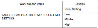
SYSTEM SETTING
Target Evaporator Temp Upper Limit
DESCRIPTION
Set the target evaporator temperature upper limit.
HOW TO SET
 With CONSULT
Perform the “TARGET EVAPORATOR TEMP UPPER LIMIT SETTING” of HVAC work support item.
DOOR MOTOR STARTING POSITION RESET
Description
- Reset signal is transmitted from A/C auto amp. to air mix door motor,
intake door motor and mode door
motor. Starting position reset can be performed.
NOTE: During reset, DEF switch indicator blinks.
- When air mix door motor, intake door motor or mode door motor is removed and installed, always perform door motor starting position reset.
Work Procedure
1.PERFORM DOOR MOTOR STARTING POSITION RESET
 With CONSULT
- Turn ignition switch ON.
- Select “Door Motor Starting Position Reset” in “ACTIVE TEST” mode of “HVAC” using CONSULT.
- Touch “Start” and wait a few seconds.
- Make sure the “COMPLETED” is displayed on CONSULT screen.
>> Inspection End.
 Wiring diagram
MANUAL AIR CONDITIONING SYSTEM
Wiring Diagram
...
 DTC/circuit diagnosis
U1000 CAN COMM CIRCUIT
Description
CAN (Controller Area Network) is a serial communication system for real time
application. It is an on-vehicle
multiplex communication system with high data comm ...
Other materials:
P0444, P0445 EVAP canister purge volume control solenoid
DTC Description
DTC DETECTION LOGIC
DTC No.
CONSULT screen terms
(Trouble diagnosis content)
DTC detecting condition
P0444
PURG VOLUME CONT/V
(Evaporative emission system purge control
valve circuit open)
An excessively low voltage signal is sent to ECM through ...
Windshield-washer fluid
Windshield-washer fluid reservoir
Fill the windshield-washer fluid reservoir periodically.
Add windshield-washer fluid when the low
windshield-washer fluid warning light comes on.
To fill the windshield-washer fluid reservoir, lift
the cap off the reservoir and pour the windshieldwasher ...
Jump starting
To start your engine with a booster battery, the
instructions and precautions below must be followed.
WARNING
If done incorrectly, jump starting can
lead to a battery explosion, resulting in
severe injury or death. It could also
damage your vehicle.
Explosive ...
