Nissan Rogue Service Manual: Component parts
Component Parts Location
|
No. |
Component |
Function |
| 1 | Key switch | Transmits the key switch signal to the BCM.
Refer to SEC-115, "Component Parts Location" (without Intelligent Key system) for detailed installation location. |
| 2 | Combination meter |
|
| 3 | ABS actuator and electric unit (control unit) | Transmits the vehicle speed signal to the combination meter via CAN
communication.
Refer to BRC-8, "Component Parts Location" for detailed installation location. |
| 4 | Parking brake switch | Transmits the parking brake switch signal to the combination meter. |
| 5 | BCM | Based on the signals received from various units and switches,
transmits the buzzer output signal
to the combination meter via CAN communication.
Refer to BCS-7, "BODY CONTROL SYSTEM : Component Parts Location" (with Intelligent Key system) or BCS-79, "BODY CONTROL SYSTEM : Component Parts Location" (without Intelligent Key system) for detailed installation location. |
| 6 | Seat belt buckle switch LH | Transmits a seat belt buckle switch signal LH to the combination meter. |
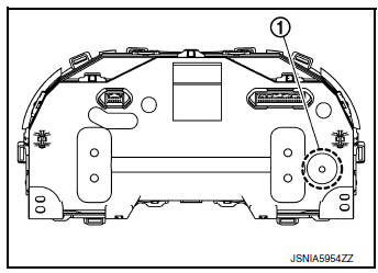
Combination Meter
The combination meter has a built-in buzzer (1) and sounds the following warnings, according to signals from each switch and unit:
- Light reminder warning
- Parking brake release warning chime
- Seat belt warning
- Key warning chime

 System
WARNING CHIME SYSTEM
WARNING CHIME SYSTEM : System Description
SYSTEM DIAGRAM (WITH INTELLIGENT KEY SYSTEM)
SYSTEM DIAGRAM (WITHOUT INTELLIGENT KEY SYSTEM)
COMBINATION METER INPUT/OUTPUT S ...
Other materials:
EVAP control system pressure sensor
Exploded View
EVAP control system pressure sensor
O-ring
EVAP canister
EVAP canister vent control valve
EVAP canister vent control valve hose
EVAP vent line
EVAP canister purge hose
Clamp
Front
Removal and Installation
NOTE:
The EVAP canister syst ...
Ignition signal
Component Function Check
1.INSPECTION START
Turn ignition switch OFF, and restart engine.
Does the engine start?
YES-1 >> With CONSULT: GO TO 2.
YES-2 >> Without CONSULT: GO TO 3.
NO >> Proceed to EC-470, "Diagnosis Procedure".
2.CHECK IGNITION SIGNAL FUNCTIO ...
CAN system (type 1)
DTC/CIRCUIT DIAGNOSIS
MAIN LINE BETWEEN IPDM-E AND DLC CIRCUIT
Diagnosis Procedure
1.CHECK CONNECTOR
Turn the ignition switch OFF.
Disconnect the battery cable from the negative terminal.
Check the following terminals and connectors for damage, bend and
loose connecti ...
