Nissan Rogue Service Manual: Steering switch
Description
When one of the steering switches is pushed, the resistance in the steering switch changes the signal to identify which button is controlling the information display.
Diagnosis Procedure
Regarding Wiring Diagram information, refer to MWI-32, "Wiring Diagram".
1.CHECK STEERING SWITCH CIRCUIT
- Turn ignition switch OFF.
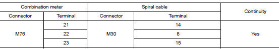
- Disconnect combination meter harness connector M76 and spiral cable harness connector M30.
- Check continuity between combination meter harness connector M76 and spiral cable harness connector M30.
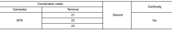
- Check continuity between combination meter harness connector M76 and ground.
Is the inspection result normal? YES >> Inspection End.
NO >> Repair or replace harness or connector.
Component Inspection
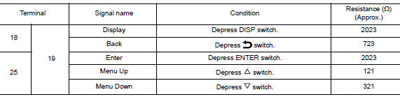
1.CHECK STEERING SWITCH RESISTANCE
Check resistance between the following steering switch terminals.
Is the inspection result normal? YES >> GO TO 2.
NO >> Replace steering wheel switch. Refer to AV-65, "Removal and Installation".
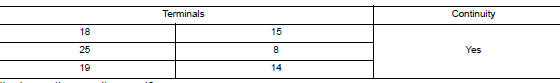
2.CHECK SPIRAL CABLE
Check continuity between the following spiral cable terminals.
Is the inspection result normal? YES >> Inspection End.
NO >> Replace spiral cable. Refer to SR-15, "Removal and Installation".
 Meter control switch signal circuit
Diagnosis Procedure
Regarding Wiring Diagram information, refer to MWI-32, "Wiring Diagram".
1.CHECK METER CONTROL SWITCH SIGNAL
Turn ignition switch ON.
Check voltage be ...
 Washer level switch signal circuit
Description
Transmits the washer fluid level switch signal to the combination meter.
Diagnosis Procedure
Regarding Wiring Diagram information, refer to MWI-32, "Wiring Diagram".
1.CHECK ...
Other materials:
Preparation
Special Service Tools
The actual shape of the tools may differ from those illustrated here.
Tool number
(TechMate No.)
Tool name
Description
—
(165-GR8-1200KIT-NI)
Multitasking battery and electrical diagnostic
station
Testing batteries, starting and ...
U1001 CAN comm circuit
Description
CAN (Controller Area Network) is a serial communication line for real time
application. It is an on-vehicle multiplex
communication line with high data communication speed and excellent error
detection ability. Many electronic
control units are equipped onto a vehicle, and each co ...
Seatback pockets
Seatback pockets
There is a pocket located on the back of the driver
and passenger seats. These pockets can be
used to store maps.
WARNINGTo ensure proper operation of the passenger’s
advanced air bag system, please observe
the following items:
Do not allow a pas ...
