Nissan Rogue Service Manual: Sample/Wiring Diagram -Example-
Each section includes wiring diagrams.
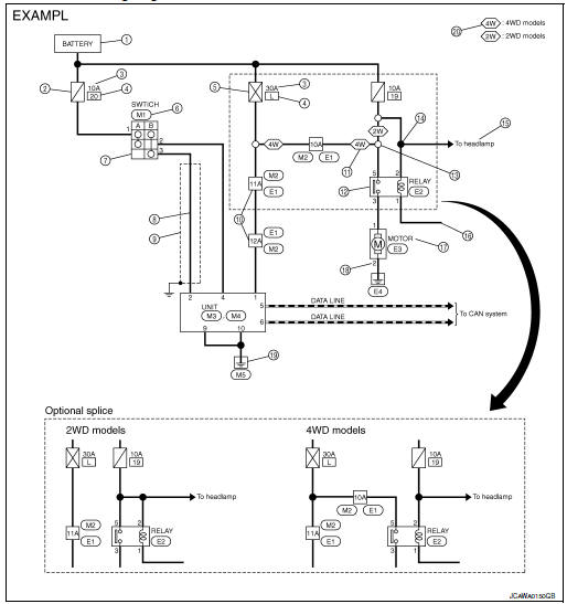
Description
| Number | Item | Description |
| 1 | Power supply |
|
| 2 | Fuse |
|
| 3 | Current rating of fusible link/fuse |
|
| 4 | Number of fusible link/ fuse |
|
| 5 | Fusible link |
|
| 6 | Connector number |
|
| 7 | Switch |
|
| 8 | Circuit (Wiring) |
|
| 9 | Shielded line |
|
| 10 | Connectors |
|
| 11 | Option abbreviation |
|
| 12 | Relay |
|
| 13 | Optional splice |
|
| 14 | Splice |
|
| 15 | System branch |
|
| 16 | Page crossing |
|
| 17 | Component name |
|
| 18 | Terminal number |
|
| 19 | Ground (GND) |
|
| 20 | Explanation of option description |
|
 ”.
”. ” means the splice.
SWITCH POSITIONS
Switches are shown in wiring diagrams as if the vehicle is in the “normal” condition.
A vehicle is in the “normal” condition when:
- ignition switch is “OFF”
- doors, hood and trunk lid/back door are closed
- pedals are not depressed
- parking brake is released
MULTIPLE SWITCH
The continuity of multiple switch is described in two ways as shown below.
- The switch chart is used in schematic diagrams.
- The switch diagram is used in wiring diagrams.
 Connector Symbols
Most of connector symbols in wiring diagrams are shown from the terminal
side.
Connector symbols shown from the terminal side are enclosed by
a single line and followed by the direction ...
 Connector Information
HOW TO USE CONNECTOR INFORMATION
Description
Number
Item
Description
1
Connector number
Alphabetic characters show to which harness the connector is
pla ...
Other materials:
Wiring diagram
BCM
Wiring Diagram
...
Fuses
Two types of fuses are used. Type A is used in
the fuse boxes in the engine compartment. Type
B is used in the passenger compartment fuse
box.
Type A fuses are provided as spare fuses. They
are stored in the passenger compartment fuse
box.
Type A fuses can be installed in the engine
co ...
DTC/circuit diagnosis
POWER SUPPLY AND GROUND CIRCUIT
BCM (BODY CONTROL SYSTEM) (WITH INTELLIGENT KEY SYSTEM)
BCM (BODY CONTROL SYSTEM) (WITH INTELLIGENT KEY SYSTEM) : Diagnosis
Procedure
Regarding Wiring Diagram information, refer to BCS-50, "Wiring Diagram".
1. CHECK FUSE
Check that the following fuse i ...
