
Nissan Rogue Service Manual: Repairing high strength steel
High Strength Steel (HSS)
High strength steel is used for body panels in order to reduce vehicle weight.
Accordingly, precautions in repairing automotive bodies made of high strength steel are described below:
|
Tensile strength |
Major applicable parts |
| 440 - 780 MPa |
|
| 980 - 1350 MPa |
|
Read the following precautions when repairing HSS:
- Additional points to consider
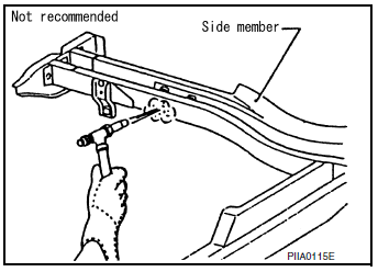
- The repair of reinforcements (such as side members) by heating
is not recommended since it may weaken the component.
When heating is unavoidable, do not heat HSS parts above 550°C (1,022°F).
Verify heating temperature with a thermometer.
(Crayon-type and other similar type thermometer are appropriate.)
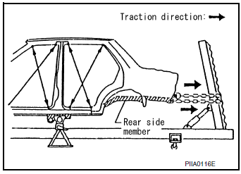
- When straightening body panels, use caution in pulling any HSS panel. Because HSS is very strong, pulling may cause deformation in adjacent portions of the body. In this case, increase the number of measuring points, and carefully pull the HSS panel.
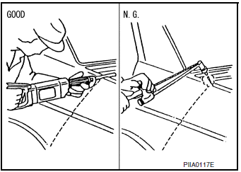
- When cutting HSS panels, avoid gas (torch) cutting if possible.
Instead, use a saw to avoid weakening surrounding areas due to heat. If gas (torch) cutting is unavoidable, allow a minimum margin of 50 mm (1.97 in).
- When welding HSS panels, use spot welding whenever possible
in order to minimize weakening surrounding areas due to
heat.
If spot welding is impossible, use MIG. welding. Do not use gas (torch) for welding because it is inferior in welding strength.

- The spot weld on HSS panels is harder than that of an ordinary
steel panel.
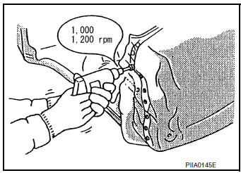
Therefore, when cutting spot welds on a HSS panel, use a low speed high torque drill (1,000 to 1,200 rpm) to increase drill bit durability and facilitate the operation.
- Precautions in spot welding HSS
This work should be performed under standard working conditions.Always note the following when spot welding HSS:
- The electrode tip diameter must be sized properly according to the metal thickness.
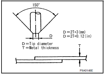
- The panel surfaces must fit flush to each other, leaving no gaps.
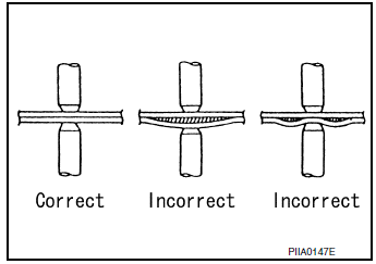
- Follow the specifications for the proper welding pitch.
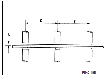
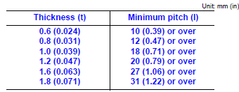
Handling of Ultra High Strength Steel Plate Parts
PROHIBITION OF CUT AND CONNECTION
Never cut and Joint the stiffener front side member (front floor inside frame parts) because its material is high strength steel plate (ultra high strength steel plate).
The front floor assembly must be replaced if this part is damaged.
 Precautions
Precaution for Supplemental Restraint System (SRS) "AIR BAG" and "SEAT
BELT
PRE-TENSIONER"
The Supplemental Restraint System such as “AIR BAG� and “SEAT BELT
PRE-TENSIO ...
 Location of plastic parts
Precautions for Plastics
CAUTION:
When repairing and painting a portion of the body adjacent to
plastic parts, consider their characteristics (influence of heat
and solvent) and re ...
Other materials:
Service data and specifications (sds)
Idle Speed
Condition
Specification
No load* (in P or N position)
650 ± 50 rpm
*: Under the following conditions
A/C switch: OFF
Electric load: OFF (Lights, heater fan & rear window defogger)
Steering wheel: Kept in straight-ahead position
...
EPS warning lamp
Component Function Check
1.CHECK THE ILLUMINATION OF THE EPS WARNING LAMP
Check that the EPS warning lamp turns ON when ignition switch turns ON. Then,
EPS warning lamp turns
OFF after the engine is started.
Is the inspection result normal?
YES >> Inspection End.
NO >> Perfor ...
Washer level switch signal circuit
Description
Transmits the washer fluid level switch signal to the combination meter.
Diagnosis Procedure
Regarding Wiring Diagram information, refer to MWI-32, "Wiring Diagram".
1.CHECK WASHER FLUID LEVEL SWITCH SIGNAL CIRCUIT
Turn ignition switch OFF.
Disconnect comb ...
