
Nissan Rogue Service Manual: Removal and installation
CHASSIS CONTROL MODULE
Exploded View
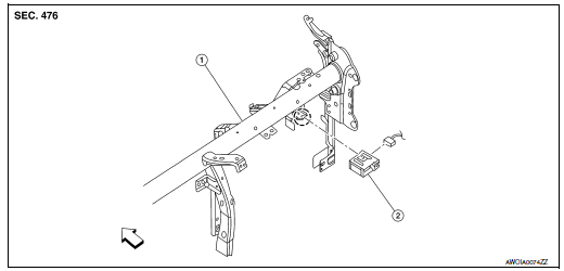
- Steering member
- Chassis control module
 Front
Front
Removal and Installation
CAUTION: When replacing chassis control module, configuration of chassis control module is required. Refer to DAS-205, "Work Procedure".
REMOVAL
NOTE: If the chassis control module is replaced, user registration information is erased, and all setting items for Nissan InTuition related parts are erased.
- Remove the glove box assembly. Refer to IP-23, "Removal and Installation".
- Release the pawl and remove the chassis control module.
CAUTION: Do not drop the chassis control module.
INSTALLATION
Installation is in the reverse order of removal.
CAUTION: When replacing the chassis control module, perform the configuration of chassis control module.
Refer to DAS-205, "Work Procedure".
 Symptom diagnosis
CHASSIS CONTROL
Active Engine Brake
NOTE:
For the operational conditions of Active Engine Brake, refer to
DAS-175, "System Description - Active
Engine Brake".
Perfor ...
 Drive Mode System
SPORT MODE ...
Other materials:
B0094 crash zone sensor
DTC Logic
DTC DETECTION LOGIC
CONSULT name
DTC
DTC detecting condition
Repair order
CRASH ZONE SENSOR
[SENSOR FAIL]
B0094
Crash zone sensor has malfunctioned.
Refer to SRC-68, "Diagnosis Procedure".
CRASH ZONE SENSOR
[COMM ...
Fusible link inspection
How To Check
A melted fusible link can be detected either by visual inspection or by
feeling with finger tip. If its condition is
questionable, use circuit tester or test lamp.
Fusible link
With stop/start system
Without stop/start system*
*: Not applicable
CAUTION:
If ...
P0607 ECM
DTC Description
DTC DETECTION LOGIC
DTC No.
CONSULT screen terms
(Trouble diagnosis content)
DTC detecting condition
P0607
ECM
(Control module performance)
ECM internal communication system is malfunctioning.
POSSIBLE CAUSE
ECM
FAIL-SAFE
Not applicable
D ...
