Nissan Rogue Service Manual: Removal and installation
NATS ANTENNA AMP.
Exploded View
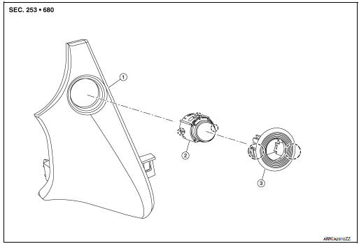
- Instrument finisher B
- Push button ignition switch
- NATS antenna amp.
 Pawl
Pawl
Removal and Installation
REMOVAL
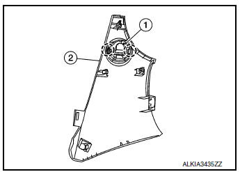
- Remove the instrument finisher B. Refer to IP-16, "INSTRUMENT FINISHER B : Removal and Installation".
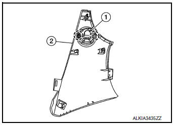
- Release pawls and remove NATS antenna amp. (1) from instrument finisher B (2).
: Pawl
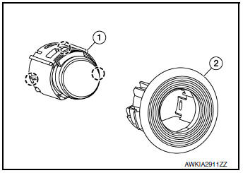
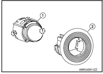
- Release pawls and remove NATS antenna amp. (2) from push
button ignition switch (1).: Pawl
INSTALLATION
Installation is in the reverse order of removal.
PUSH-BUTTON IGNITION SWITCH
Exploded View
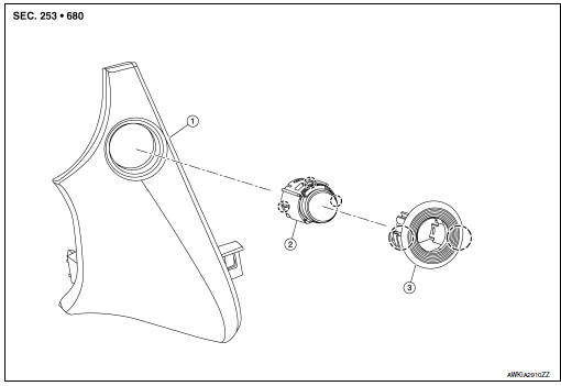
- Instrument finisher B
- Push button ignition switch
- NATS antenna amp.
Pawl
Removal and Installation
REMOVAL
- Remove the instrument finisher B. Refer to IP-16, "INSTRUMENT FINISHER B : Removal and Installation".
- Release pawls and remove NATS antenna amp. (1) from instrument
finisher B (2).: Pawl
- Release pawls and remove NATS antenna amp. (2) from push
button ignition switch (1).: Pawl
INSTALLATION
Installation is in the reverse order of removal.
 Symptom diagnosis
ENGINE DOES NOT START WHEN INTELLIGENT KEY IS INSIDE OF VEHICLE
Description
Engine does not start when push-button ignition switch is pressed while
carrying Intelligent Key.
NOTE:
Check ...

Other materials:
Front and rear washer motor
Exploded View
Washer tank
Front and rear washer motor
Rear view camera washer motor
Seal
Rear washer outlet
Front washer out
Removal and Installation
REMOVAL
Drain washer fluid.
Remove front fender protector (RH). Refer to EXT-28, "FENDER
PROTECTOR ...
System features
System features
NISSAN Voice Recognition can activate the following
systems:
Bluetooth™ Hands-Free Phone System
Navigation
Audio
Information
My Apps
For additional information on the navigation system,
refer to the separate Navigation System
Own ...
Steering switch
Description
When one of the steering switches is pushed, the resistance in the steering
switch changes the signal to
identify which button is controlling the information display.
Diagnosis Procedure
Regarding Wiring Diagram information, refer to MWI-32, "Wiring Diagram".
1.CHECK STE ...
