Nissan Rogue Service Manual: Rear regulator
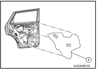
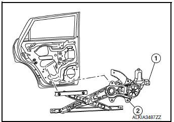
Exploded View
- Rear door panel
- Rear door glass corner finisher
- Rear door glass rear run channel
- Rear door regulator assembly
- Rear door glass power window motor
- Rear door glass
- Rear door glass rubber run channel
Removal and Installation
REMOVAL
- Remove the rear door finisher. Refer to INT-18, "Removal and Installation".
- Remove vapor barrier.
- Temporarily reconnect the rear power window switch.
- Operate the rear power window switch to raise/lower the rear door glass until the rear door glass regulator to rear door glass bolts (A) can be seen and remove.
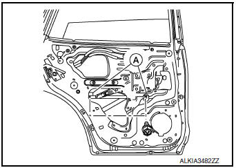
- Raise the rear door glass and hold in place with suitable tool (A).

- Remove the bolts (B) and nuts (A) from the rear door glass regulator (1).
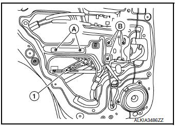
- Disconnect the harness connector from the rear door regulator (1).
- Remove rear door regulator (2).
INSPECTION AFTER REMOVAL
Check the rear door glass regulator for the following items:
- Gear wear
- Rear door glass regulator deformation
- Spring damage
- Grease condition for each sliding part
If a malfunction is detected, replace or grease it.
INSTALLATION
Installation is in reverse order of removal.
CAUTION:
- Tighten the rear door regulator to specification Refer to GW-22, "Exploded View"
 Rear door glass
Exploded View
Rear door panel
Rear door glass corner finisher
Rear door glass rear run channel
Rear door glass regulator assembly
Rear door glass power window motor
Rear door glas ...
 Rear power window motor
Removal and Installation
REMOVAL
Remove rear door glass regulator. Refer to GW-22, "Removal and
Installation".
Remove screws (A) and rear door power window motor (1) fr ...
Other materials:
Towing safety
Trailer hitch
Your vehicle may be equipped with an optional
trailer tow package. The trailer tow package includes
a receiver-type frame mounted hitch. This
hitch is rated for the maximum towing capacity of
this vehicle when the proper towing equipment is
used. Choose a proper ball mount and hi ...
B0020 side airbag module IH
Description
DTC B0020 FRONT LH SIDE AIR BAG MODULE
The front LH side air bag module is wired to the air bag diagnosis sensor
unit. The air bag diagnosis sensor
unit will monitor for opens and shorts in detected lines to the front LH side
air bag module.
PART LOCATION
Refer to SRC-6, "C ...
Parking brake switch signal circuit
Component Function Check
1.CHECK PARKING BRAKE SWITCH OPERATION
Check that brake warning lamp in combination meter turns ON/OFF when parking
brake is actuated.
Is the inspection result normal?
YES >> Inspection End.
NO >> Proceed to diagnosis procedure. Refer to WCS-45, " ...
