Nissan Rogue Service Manual: Rear door glass
Exploded View
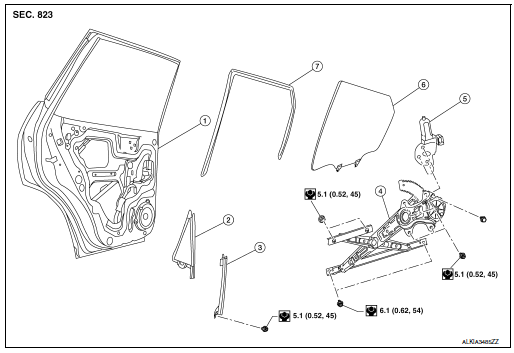
- Rear door panel
- Rear door glass corner finisher
- Rear door glass rear run channel
- Rear door glass regulator assembly
- Rear door glass power window motor
- Rear door glass
- Rear door glass rubber run channel
Removal and Installation
REMOVAL
- Remove the rear door finisher. Refer to INT-18, "Removal and Installation".
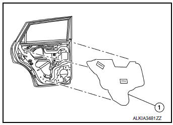
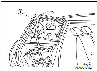
- Remove the rear door vapor barrier (1).
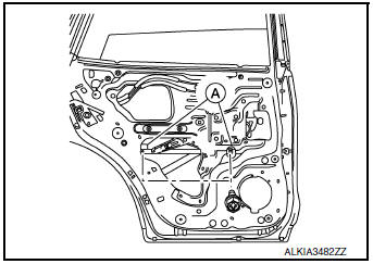
- Temporarily reconnect the rear power window switch.
- Operate the rear power window switch to raise/lower the rear door glass until the rear door glass regulator to rear door glass bolts (A) can be seen and remove.
- Remove screws and rear door corner finisher (1).
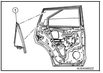
- Remove the rear door glass (1).
INSTALLATION
Installation is in the reverse order of removal.
CAUTION: • Tighten the rear door regulator bolts to glass specification. Refer to GW-22, "Exploded View"
FITTING INSPECTION
- Check that the rear door glass is securely fit into the rear door glass run channel.
- Lower the rear door glass slightly [approximately 10 to 20 mm (0.39 to 0.79 in)], and check that the clearance to the sash is parallel. If the clearance between the rear door glass and sash is not parallel, loosen the rear door regulator to glass bolts, rear door run channel bolts, and rear door glass bolts to correct the rear door glass position.
 Front power window motor
Removal and Installation
REMOVAL
Remove front door glass regulator. Refer to GW-16, "Removal and
Installation".
Remove screws (A) and front power window motor (1) from ...
 Rear regulator
Exploded View
Rear door panel
Rear door glass corner finisher
Rear door glass rear run channel
Rear door regulator assembly
Rear door glass power window motor
Rear door glass
& ...
Other materials:
CAN system (type 4)
MAIN LINE BETWEEN IPDM-E AND DLC CIRCUIT
Diagnosis Procedure
1.CHECK CONNECTOR
Turn the ignition switch OFF.
Disconnect the battery cable from the negative terminal.
Check the following terminals and connectors for damage, bend and
loose connection (connector side
an ...
Glass lid
Exploded View
Panoramic roof glass
Glass lid
Side trim covers (LH/RH)
Front drain hose (LH/RH)
Moonroof motor assembly
Sunshade motor assembly
Moonroof front bracket (LH/RH)
Moonroof rear bracket (LH/RH)
Rear drain hose (LH/RH)
Moonroof unit assembly ...
Ignition switch (if so equipped)
WARNING
Never remove or turn the key to the
LOCK position while driving. The steering
wheel will lock (for models with a
steering lock mechanism). This may
cause the driver to lose control of the
vehicle and could result in serious vehicle
damage or personal ...
