
Nissan Rogue Service Manual: Basic inspection
DIAGNOSIS AND REPAIR WORKFLOW
Work Flow
OVERALL SEQUENCE
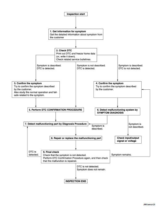
DETAILED FLOW
1.GET INFORMATION FOR SYMPTOM
- Get detailed information from the customer about the symptom (the condition and the environment when the incident/malfunction occurs).
- Check operation condition of the function that is malfunctioning.
>> GO TO 2.
2.CHECK DTC
- Check DTC.
- Perform the following procedure if DTC is detected.
- Record DTC and freeze frame data (Print them out using CONSULT.)
- Erase DTC.
- Study the relationship between the cause detected by DTC and the symptom described by the customer.
- Check related service bulletins for information.
Are any symptoms described and any DTC detected? Symptom is described, DTC is detected>>GO TO 3.
Symptom is described, DTC is not detected>>GO TO 4.
Symptom is not described, DTC is detected>>GO TO 5.
3.CONFIRM THE SYMPTOM
Try to confirm the symptom described by the customer.
Also study the normal operation and fail-safe related to the symptom.
Verify relation between the symptom and the condition when the symptom is detected.
>> GO TO 5.
4.CONFIRM THE SYMPTOM
Try to confirm the symptom described by the customer.
Verify relation between the symptom and the condition when the symptom is detected.
>> GO TO 6.
5.PERFORM DTC CONFIRMATION PROCEDURE
Perform DTC CONFIRMATION PROCEDURE for the detected DTC, and then check that DTC is detected again. At this time, always connect CONSULT to the vehicle, and check self diagnostic results in real time.
If two or more DTCs are detected, refer to BCS-47, "DTC Inspection Priority Chart" (BCM) (with Intelligent Key System) or BCS-107, "DTC Inspection Priority Chart" (BCM) (without Intelligent Key System) or PCS- 12, "Reference Value" (IPDM E/R), and determine trouble diagnosis order.
NOTE:
- Freeze frame data is useful if the DTC is not detected.
- Perform Component Function Check if DTC CONFIRMATION PROCEDURE is not included on Service Manual. This simplified check procedure is an effective alternative though DTC cannot be detected during this check.
If the result of Component Function Check is NG, it is the same as the detection of DTC by DTC CONFIRMATION
PROCEDURE.
Is DTC detected? YES >> GO TO 7.
NO >> Check according to GI-41, "Intermittent Incident".
6.DETECT MALFUNCTIONING SYSTEM BY SYMPTOM DIAGNOSIS
Detect malfunctioning system according to SYMPTOM DIAGNOSIS based on the confirmed symptom in step 4, and determine the trouble diagnosis order based on possible causes and symptom.
Is the symptom described? YES >> GO TO 7.
NO >> Monitor input data from related sensors or check voltage of related module terminals using CONSULT.
7.DETECT MALFUNCTIONING PART BY DIAGNOSTIC PROCEDURE
Inspect according to Diagnostic Procedure of the system.
Is malfunctioning part detected? YES >> GO TO 8.
NO >> Check according to GI-41, "Intermittent Incident".
8.REPAIR OR REPLACE THE MALFUNCTIONING PART
- Repair or replace the malfunctioning part.
- Reconnect parts or connectors disconnected during Diagnostic Procedure again after repair and replacement.
- Check DTC. If DTC is detected, erase it.
>> GO TO 9.
9.FINAL CHECK
When DTC is detected in step 2, perform DTC CONFIRMATION PROCEDURE again, and then check that the malfunction is repaired securely.
When symptom is described by the customer, refer to confirmed symptom in step 3 or 4, and check that the symptom is not detected.
Is DTC detected and does symptom remain? YES-1 >> DTC is detected: GO TO 7.
YES-2 >> Symptom remains: GO TO 4.
NO >> Before returning the vehicle to the customer, always erase DTC.
INSPECTION AND ADJUSTMENT
ADDITIONAL SERVICE WHEN REPLACING CONTROL UNIT
ADDITIONAL SERVICE WHEN REPLACING CONTROL UNIT : Description
CAUTION:
- When the IPDM E/R is replaced or disconnected and reconnected, perform “SENSOR INITIALIZE� with CONSULT.
ADDITIONAL SERVICE WHEN REPLACING CONTROL UNIT : Special Repair Requirement
1.SENSOR INITIALIZE
 CONSULT WORK SUPPORT
Perform “SENSOR INITIALIZE�. Refer to EXL-85, "SENSOR INITIALIZE : Special Repair Requirement".
>> WORK END
SENSOR INITIALIZE
SENSOR INITIALIZE : Description
HEADLAMP AIMING CONTROL SYSTEM
Perform the sensor initialize when installing, removing and replacing the auto levelizer control unit or suspension components.
SENSOR INITIALIZE : Special Repair Requirement
CAUTION: If performing aiming adjustment after the levelizer initialization, be sure to start the engine after turning ignition switch OFF.
1.VEHICLE CONDITION CHECK
- Park the vehicle in the straight-forward position.
- Unload the vehicle (no passenger aboard).
>> GO TO 2.
2.SENSOR INITIALIZE
CONSULT WORK SUPPORT
- Select “SENSOR INITIALIZE� of IPDM E/R work support item.
- Select “START�.
- When “INITIALIZE COMPLETE�, select “END�.
CAUTION: If “INITIALIZE NOT DONE� is indicated, auto levelizer control unit detects that the sensor lever signal was changing. The sensor initialization is cancelled. In this case, turn the ignition switch OFF, do not allow the vehicle height to change. Perform the sensor initialization again.
Is the sensor initialize completed? YES >> GO TO 3.
NO >> Perform the sensor initialize again.
3.SELF-DIAGNOSIS RESULT CHECK
Perform the self-diagnosis with CONSULT. Check that any DTC is not detected.
Is any DTC detected? YES >> GO TO 2.
NO >> Sensor initialize completed.
 Wiring diagram
HEADLAMP
Wiring Diagram
DAYTIME LIGHT SYSTEM
Wiring Diagram
AUTO LIGHT SYSTEM
Wiring Diagram
FRONT FOG LAMP SYST ...
 DTC/circuit diagnosis
POWER SUPPLY AND GROUND CIRCUIT
BCM (BODY CONTROL SYSTEM) (WITH INTELLIGENT KEY SYSTEM)
BCM (BODY CONTROL SYSTEM) (WITH INTELLIGENT KEY SYSTEM) : Diagnosis
Procedure
Regarding Wiring Diagram infor ...
Other materials:
Removal and installation
CHASSIS CONTROL MODULE
Exploded View
Steering member
Chassis control module
Front
Removal and Installation
CAUTION:
When replacing chassis control module, configuration of chassis control module
is required. Refer to
DAS-205, "Work Procedure".
REMOVAL
NOTE:
...
Basic inspection
DIAGNOSIS AND REPAIR WORKFLOW
Work Flow
OVERALL SEQUENCE
DETAILED FLOW
1.GET INFORMATION FOR SYMPTOM
Get detailed information from the customer about the symptom (the
condition and the environment when
the incident/malfunction occurs).
Check operation condition of the ...
Preparation
Special Service Tool
The actual shape of the tools may differ from those illustrated here.
Tool number
(TechMate No.)
Tool name
Description
—
(J-46534)
Trim Tool Set
Removing trim components
...
