
Nissan Rogue Service Manual: Rear bumper
Exploded View
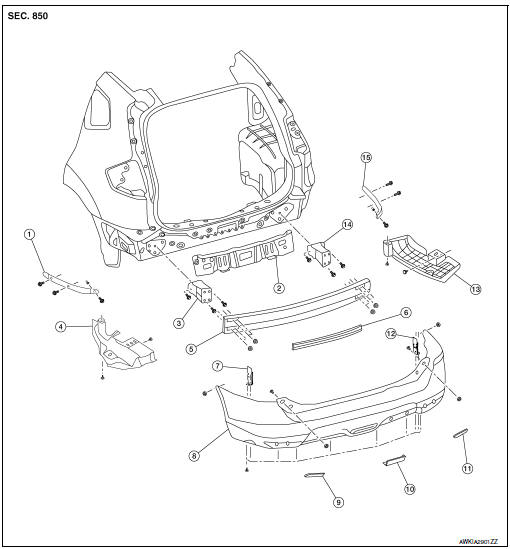
- Rear bumper fascia side bracket (LH)
- Rear mud protector
- Rear bumper reinforcement support (LH)
- Rear bumper fascia undercover (LH)
- Rear bumper reinforcement
- Rear energy absorber
- Rear bumper bracket (LH)
- Rear bumper fascia
- Rear bumper fascia reflector (LH)
- Rear bumper finisher
- Rear bumper fascia reflector (RH)
- Rear bumper bracket (RH)
- Rear bumper fascia undercover (RH)
- Rear bumper reinforcement support (RH)
- Rear bumper fascia side bracket (RH)
Removal and Installation
REMOVAL
CAUTION: Bumper fascia is made of resin. Use care when handling to prevent damage. Avoid contact with oily substances.
- Partially remove rear over fender molding. Refer to EXT-32, "REAR OVER FENDER : Exploded View".
- Partially remove rear wheel house protector. Refer to EXT-29, "REAR WHEEL HOUSE PROTECTOR : Removal and Installation".
- Remove clips and remove rear bumper fascia undercover (LH/RH) then
remove rear mud guard (LH/RH).
Refer to EXT-34, "Removal and Installation".
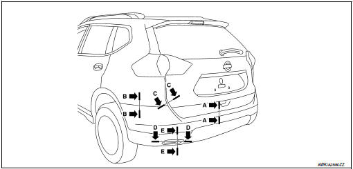
- Remove rear bumper fascia upper screws (A).
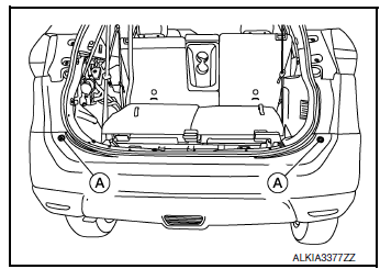
- Remove rear bumper fascia screw (A) (LH/RH).

- Disconnect harness connector from rear sonar sensors (if equipped).
- Release pawls (LH/RH) using a suitable tool and remove rear
bumper fascia.
: Pawl
CAUTION: When removing rear bumper fascia, two people are required to avoid damaging.
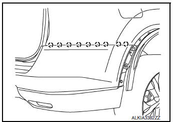
- Remove energy absorber.
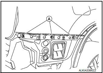
- Remove bolts (A) and remove rear bumper side bracket (LH/RH) (if necessary).
- Remove rear bumper reinforcement nuts (LH/RH), then remove rear bumper reinforcement (if necessary).
- Remove bumper stay bolts, then remove bumper stay (if necessary).
- Remove rear bump reinforce support bolts and rear bumper reinforcement (LH/RH).
INSTALLATION
Installation is in the reverse order of removal.
NOTE:
- The following table shows the specified values for checking normal installation status.
- Fitting adjustment cannot be performed.

 Front bumper
Exploded View
Front bumper fascia side
bracket (RH)
Front bumper reinforcement
support (RH)
Front bumper reinforcement
Front energy absorber
Front lower grille
Front fog lamp ( ...
 Front grille
Exploded View
Front bumper fascia
Front camera (if equipped)
Front grille
Front emblem
Pawl
Clip
Removal and Installation
REMOVAL
Remove front grille upper clip (A) ...
Other materials:
Basic inspection
DIAGNOSIS AND REPAIR WORKFLOW
Work Flow
WORK FLOW
DETAILED FLOW
1. REVIEW CUSTOMER COMPLAINT
Review customer complaint. Try to obtain detailed information about the
conditions when the symptom occurs.
>> GO TO 2.
2. VERIFY THE SYMPTOM
Verify the symptom by performing an operation ...
ECU diagnosis information
AUDIO UNIT
Reference Value
TERMINAL LAYOUT
PHYSICAL VALUES
...
Audio operation precautions
Compact disc (CD) player
CAUTION
Do not force a compact disc into the CD
insert slot. This could damage the CD
and/or CD player.
Trying to load a CD with the CD door
closed could damage the CD and/or CD
player.
Only one CD can be loaded into ...
